- Table of Contents
- Intro
- Problem Definition
- Explorations
- Solution
- Data Analysis
- Test Variance And Limits
- Conclusions
- Comments
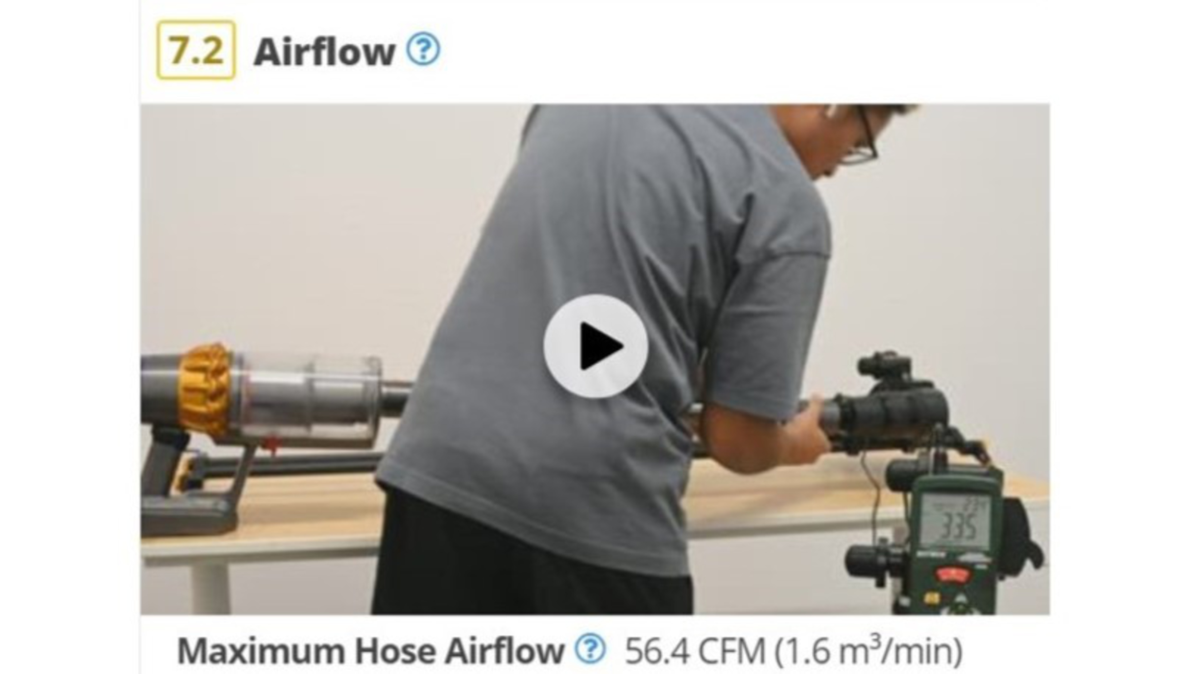
This article provides an in-depth analysis of the development of the new Airflow test within our vacuum reviews. The airflow test is designed as a supplement to the existing suction test. In brief, we use a customized anemometer to measure the airflow generated by each vacuum running at its highest setting. This test yields the maximum airflow generated by each vacuum in cubic feet per minute. We validated the new methodology by testing 25 products to confirm that the test applied to a wide range of vacuum types. It'll be a permanent addition to all our reviews moving forward. During the development of this test, we specifically explored the effect of different hose shapes, vacuum types, and other differences between most common vacuums. The result of this development work is an airflow test that provides data that's comparable across multiple vacuum types and can more easily quantify the capabilities of a vacuum's motor and its integration in a vacuum body up to the end of the main hose.
Problem Definition
The Problem
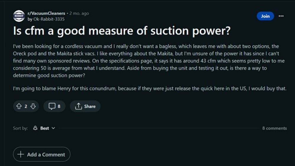
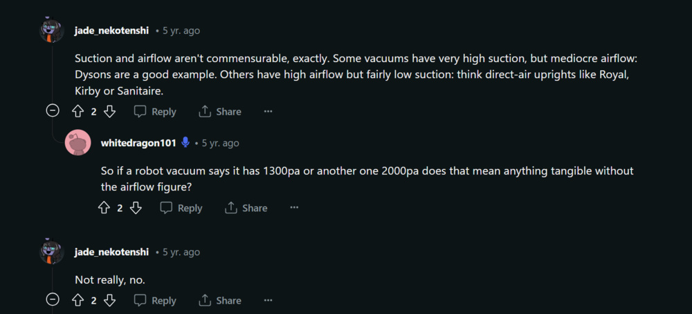
Individuals looking to buy a vacuum want to know the numeric airflow value of the models we test to help them make better purchasing decisions. Since manufacturers and consumers know the importance of airflow in the product they design and buy, airflow or other closely related values like airwatts are often included in the specifications of the product but are also often discussed on websites and forums like reddit.com/r/VacuumCleaners. For example, multiple people often mention or question the importance of airflow in their buying decisions, as we can see here.
Evidence
Suction and airflow are two characteristics that play a large part in dictating vacuum performance. The relationship between the two is inversely proportional. The higher the suction, the lower the airflow. You can see a clear example of this in the graph below, which illustrates the relationship between suction and airflow at different orifice diameters. Suction is at its highest when the orifice size is zero, which is to say completely closed, so no air is moving through the system. The opposite is true: airflow increases with the size of the orifice it passes through.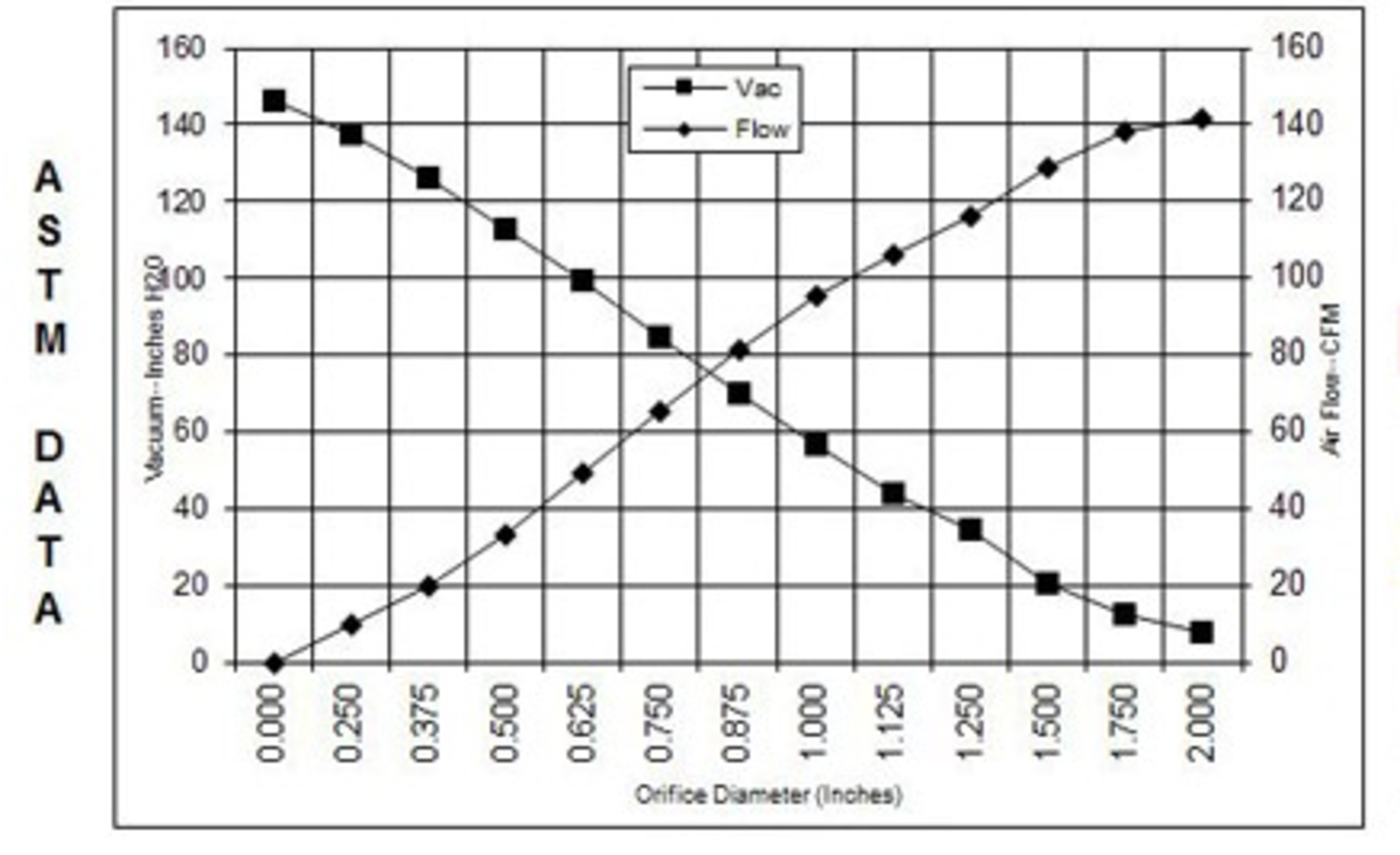
While the current vacuum reviews include an evaluation of suction, it doesn't touch on airflow. Considering the significant link between suction and airflow, measuring the latter helps provide a far more complete picture of overall vacuum performance than just measuring suction alone.
Proof Of Success
For the test to be considered successful, we want to see that canister vacuums generate the highest airflow due to their often simpler designs, which have a minimal impact on airflow, as well as their larger bodies that allow for bigger, more powerful motors. In descending order of expected airflow results, we generally expect uprights to follow close behind canisters, then stick, and then robot vacuums.
Another observation we expect to see is a clear difference between corded and cordless vacuum. Corded vacuums should generate more airflow than cordless vacuums, as a battery doesn't limit their motors.
Of course, achieving consistent measurements across different passes on the same vacuum is also important.
Explorations
Real-World Scenario Setup
Our first iteration was to test the airflow in a real-world scenario. The idea was to create a hole in an area where we would vacuum over and measure the airflow at the other end of the hole.
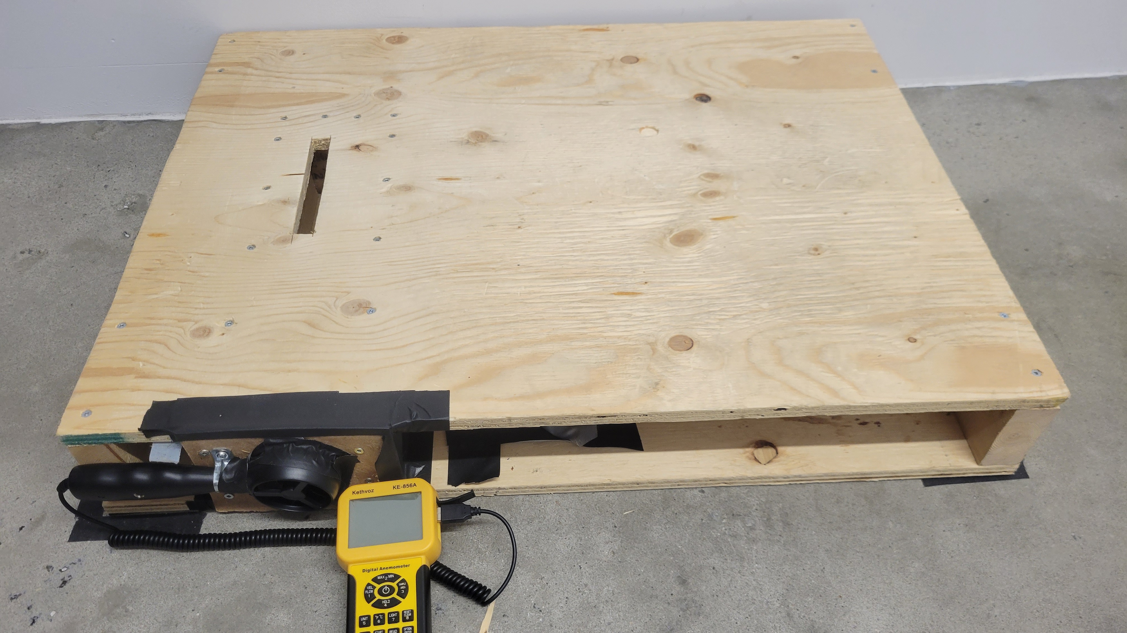
The lack of reliability in this methodology is immediately evident when we test a vacuum with adjustable head height, like the BISSELL CleanView/CleanView Swivel Pet Rewind. As shown in the following table, when the vacuum head is raised, measured airflow decreases. This decrease is erroneous since the vacuum motor generates the same airflow; the only thing being changed is the head height.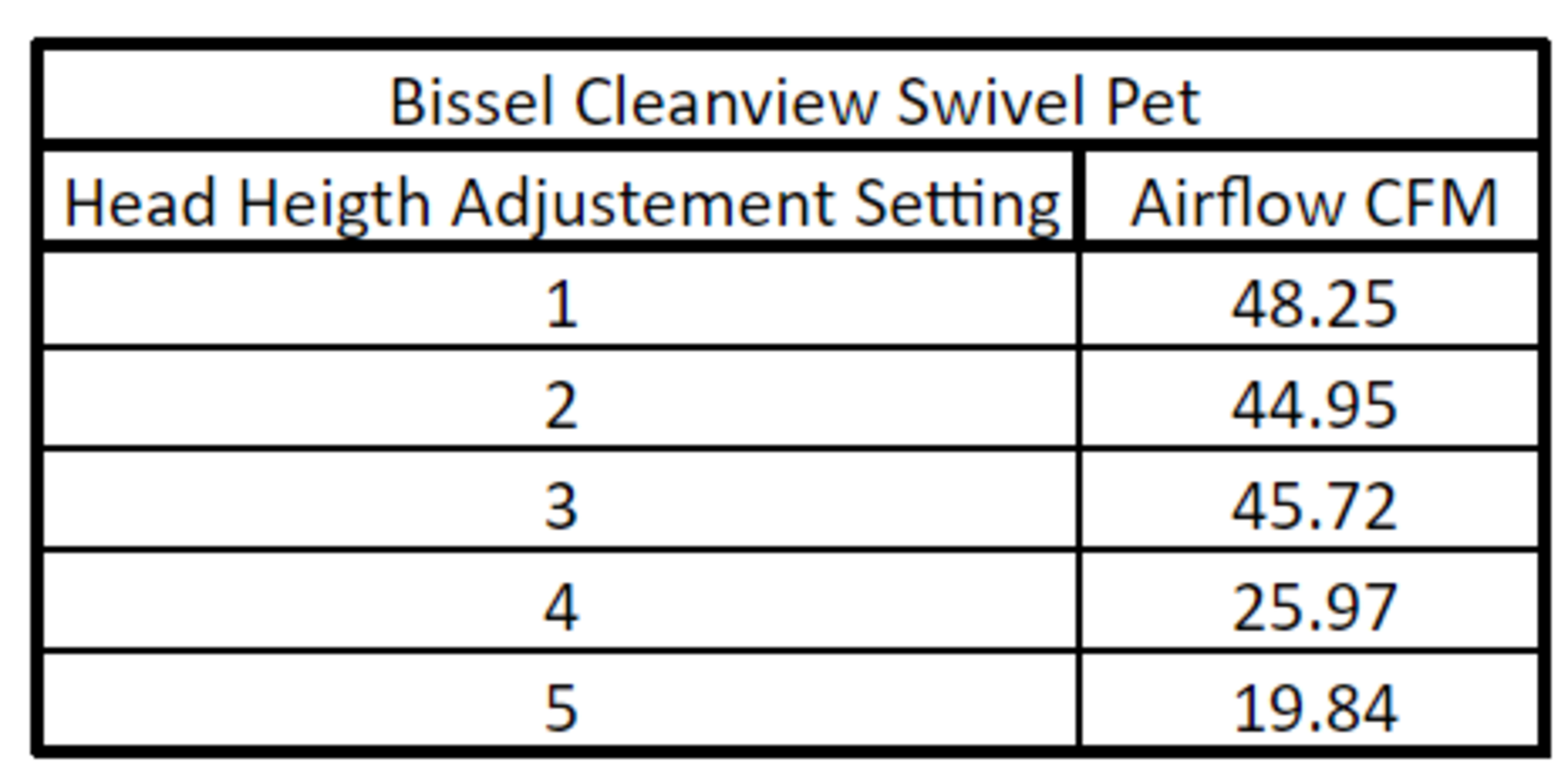
There's an improper control volume for the airflow measurements in this testing setup; since the anemometer can only measure the air going through the slit, it's not measuring all the airflow generated by the vacuum that comes from the side of the vacuum head. While we could improve airflow measurements at the vacuum head by modifying the test rig or sealing the head to the rig, we decided against it. This decision was made to have a test methodology that would apply to a wider variety of vacuums. There are a lot of variances in the head design between the different vacuums on the market. Making a test rig that would accommodate all the different types would be very time-intensive, and we would still run the risk of values being impacted by inconsistencies between each head type and the individual necessary modifications made to the rig.
To ensure the measurements provided by the test are comparable, we decided to measure at the end of the hose instead of at the head. While we lose the ability to determine the impact of head design on airflow, we can consistently measure the entirety of the airflow generated by the motor before reaching the head. For those reasons, measuring from the hose for a non-robot vacuum was a better way to measure in the most repeatable and reliable way.
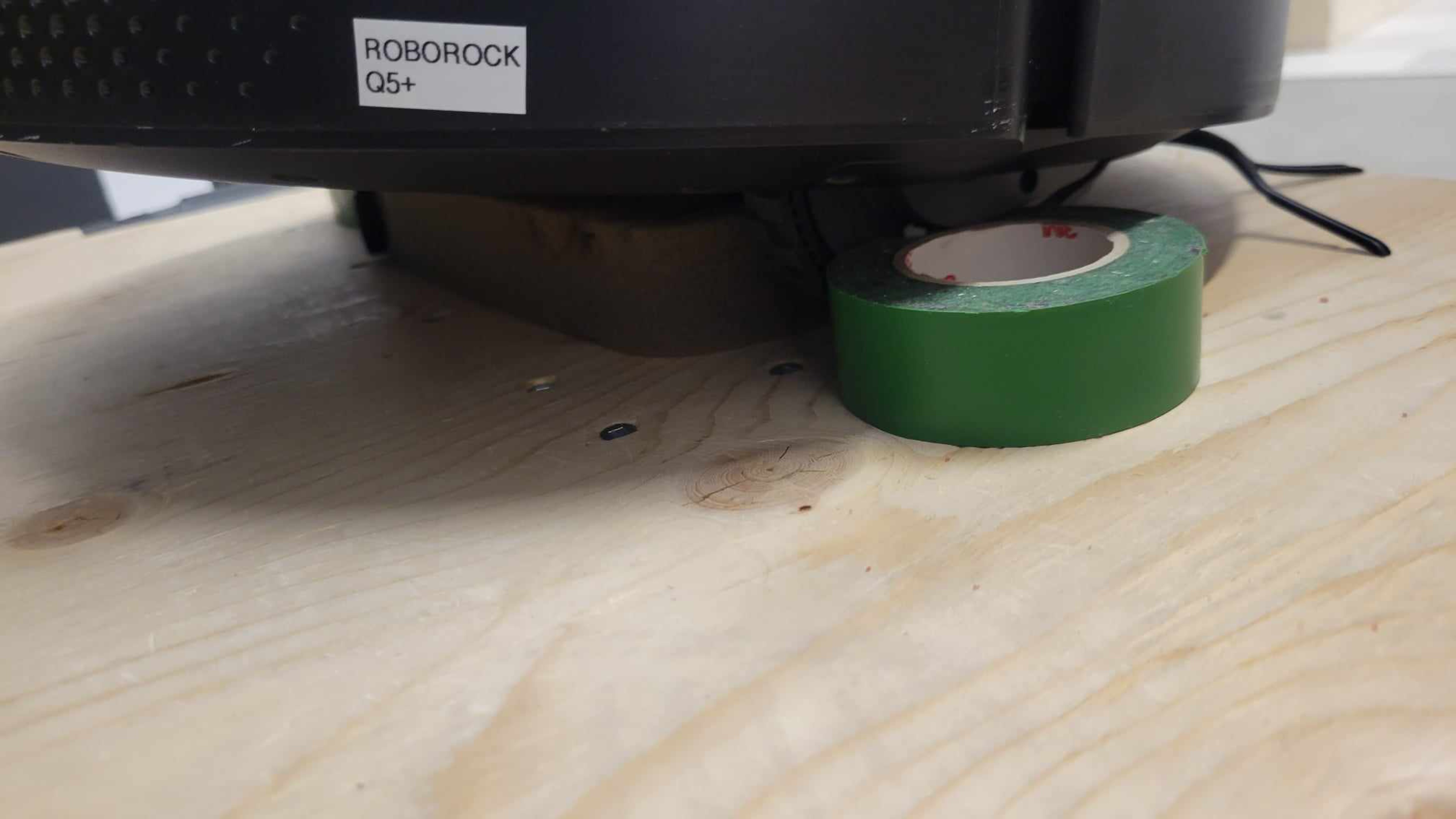
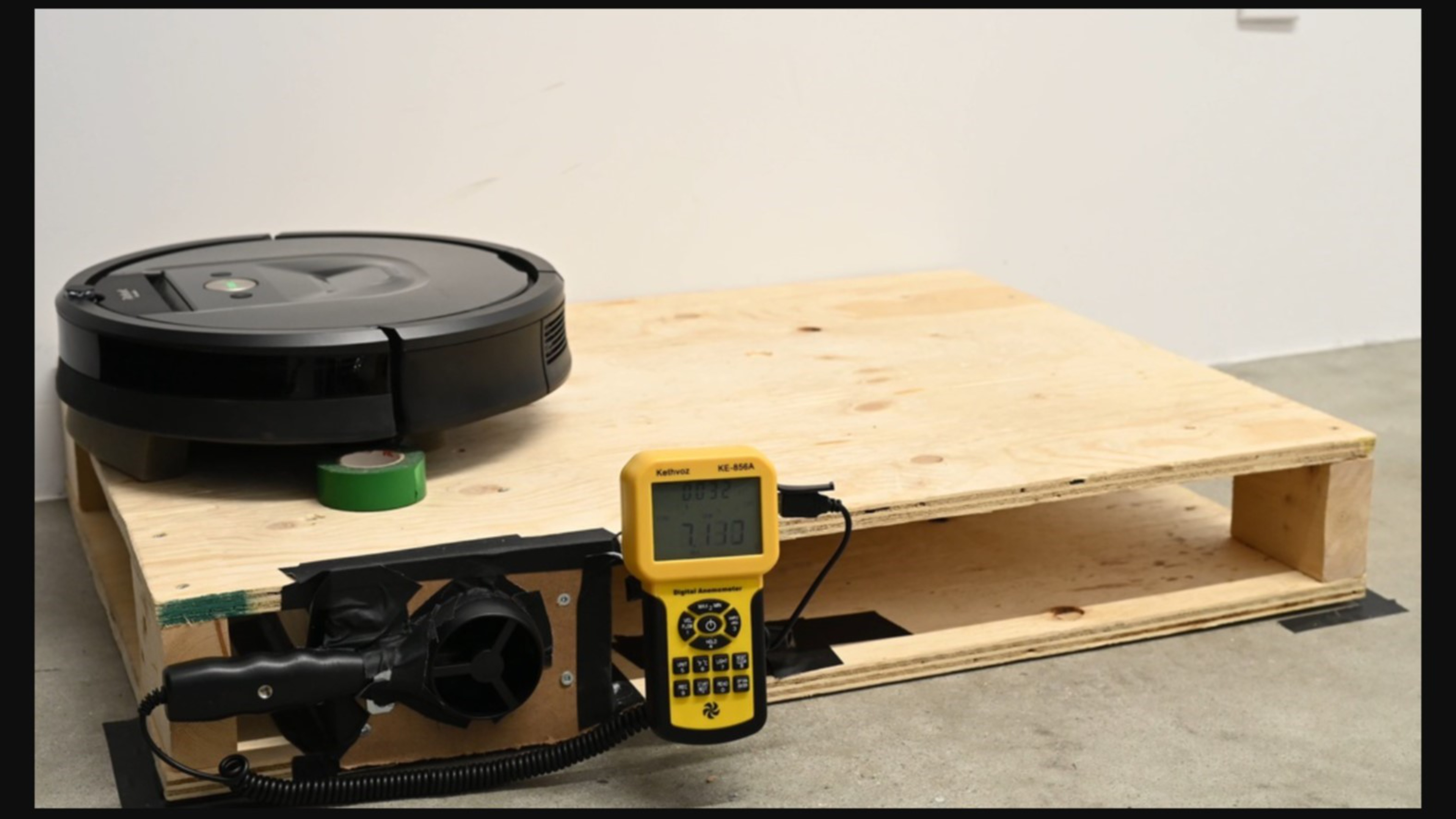
Since robot vacuums don't have hoses but often share very similar designs, the robovac testing rig has foam to seal the cleaning head to the apparatus. Note that this difference in testing methodology means that airflow measurements between robot and non-robot vacuums aren't directly comparable.
Room Temperature And Its Impact On The Test
We also sought to determine what impact air temperature has on the airflow measurements and if control of that variable would be necessary. As air temperature increases, its density decreases, as described by the volume correction factor. This inverse relationship is shown in the data in this table.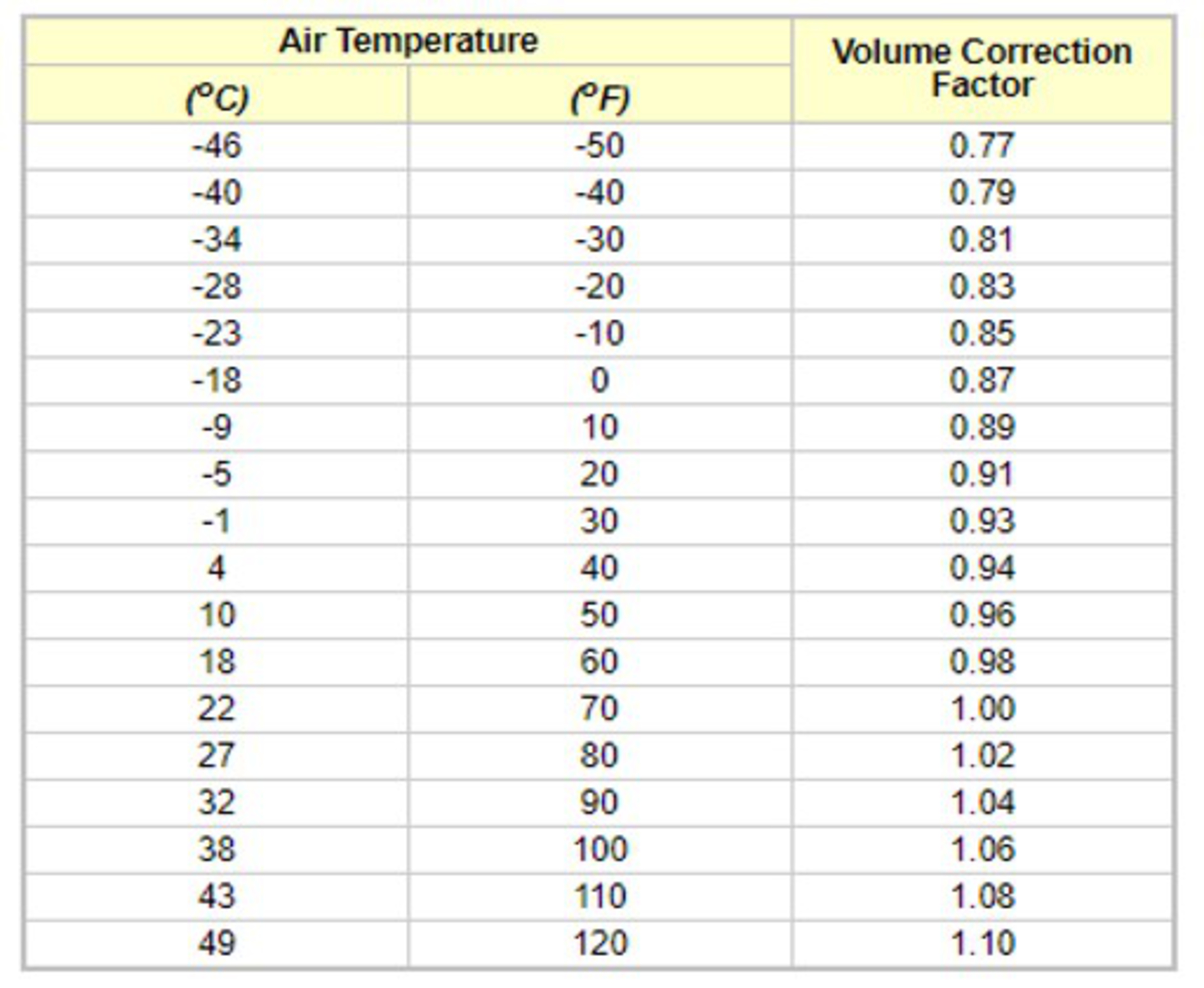
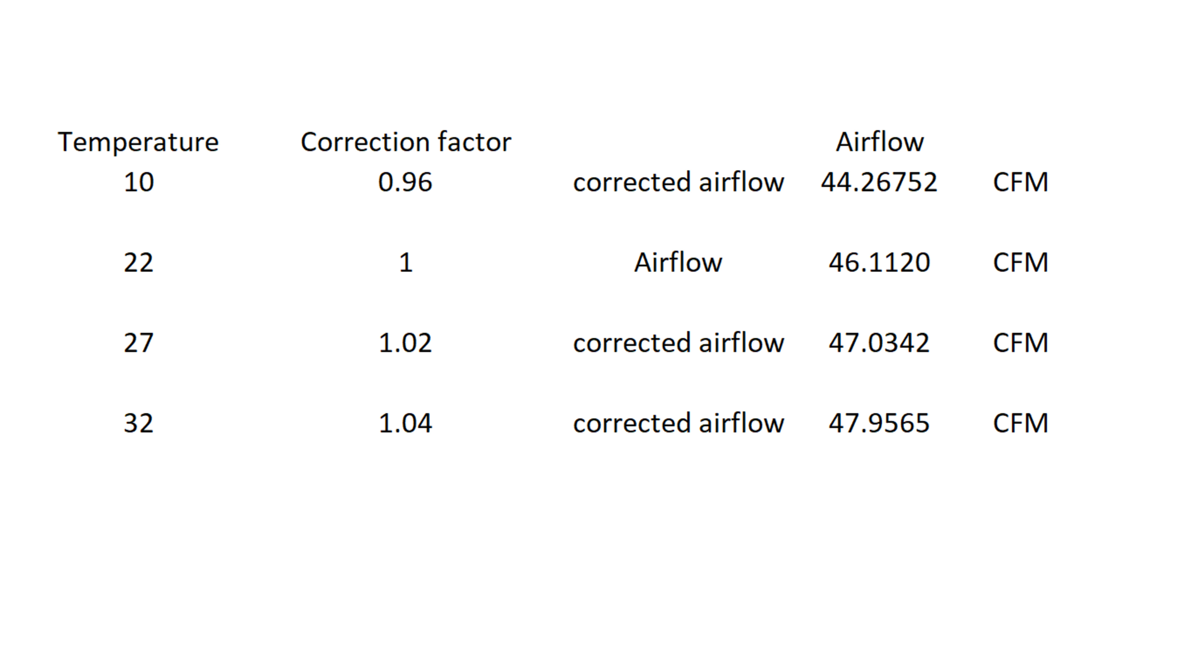
However, air temperature in the lab doesn't vary enough to appreciably affect the results of the airflow tests. Indeed, even over an extreme range of temperatures from 10 to 32 °C, airflow would only vary by three cubic feet per minute (CFM), as shown in the next image. Using the data in the following table, we can see that this is a rather negligible 4.0% change in airflow from the measurement at the normal lab air temperature of 22 °C and the fictional airflow at 32 °C.
Different Places To Measure The Airflow From
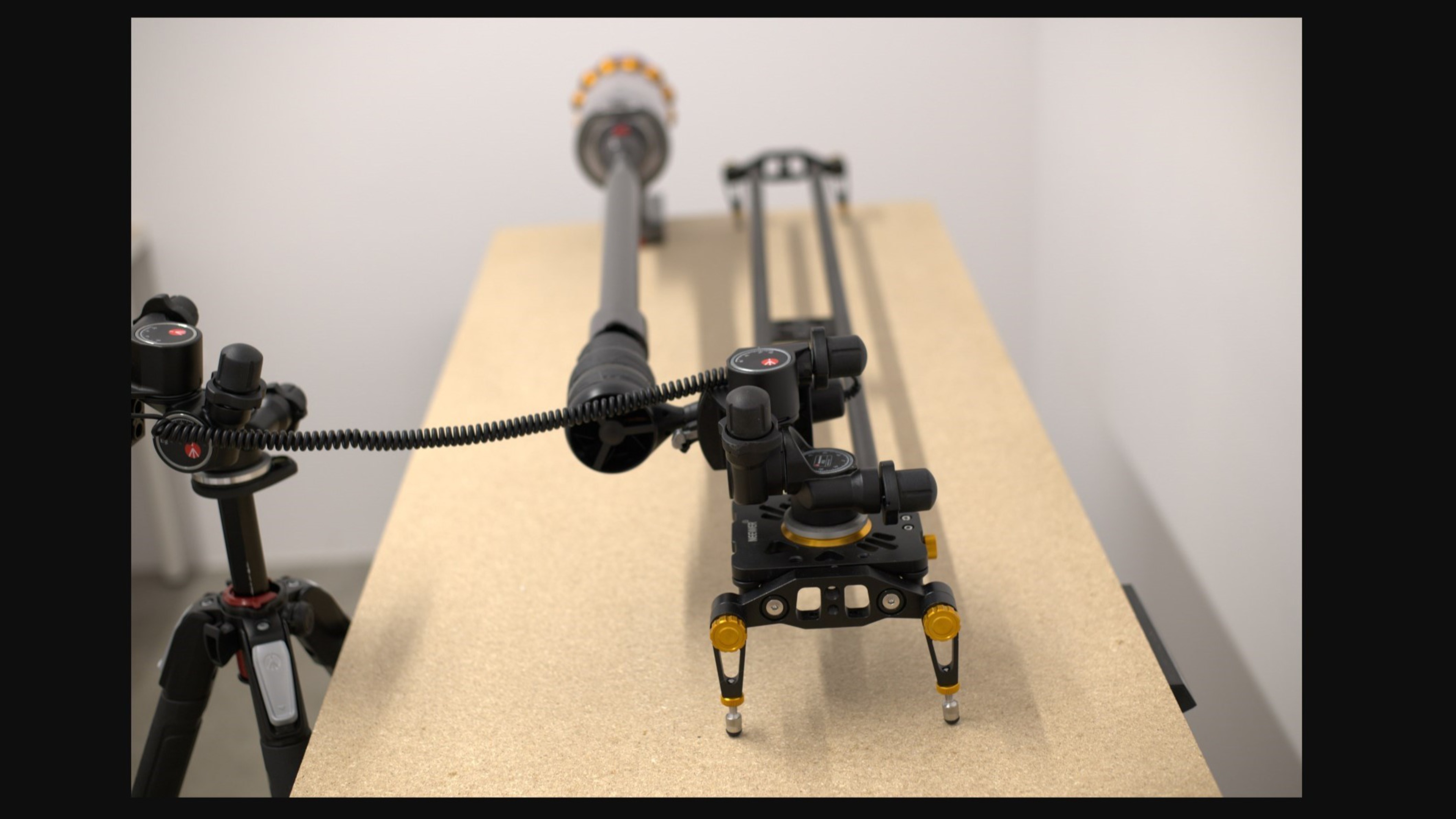
We also needed to determine a location to measure airflow that simultaneously balanced testing practicality with yielding meaningful values. Ideally, we would always measure airflow directly at the motor or at the end of the head. However, this isn't possible on most vacuums since access to the motor is often limited, and as previously mentioned, measuring at the head can be unreliable or difficult to compare when considering all vacuum designs. Further, there are numerous hose types on the cohort of vacuums tested at RTINGS.com. All of this must be considered when choosing a single measurement location across all products.
To evaluate the impact of anemometer placement, we measured airflow at different locations on the vacuum. The vacuum power setting was held constant throughout testing in the table below.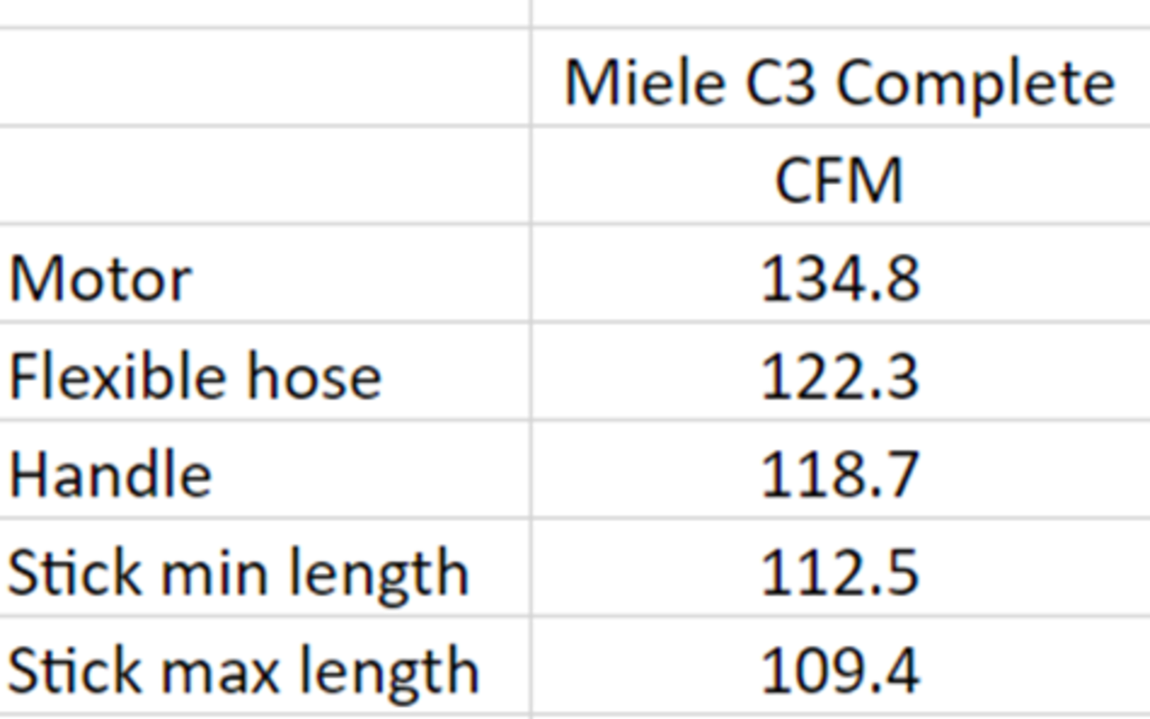
The airflow measurements decrease with distance from the motor, as expected. Based on this short observation, it is important to remember that there can be a significant difference in airflow measurements depending on where we place the anemometer. Sticking to a consistent method is important to ensure that the data we obtain is comparable across a range of vacuums. Ultimately, we decided to measure airflow at the hose since this location is constantly accessible on all the vacuums we've tested, although the raw capabilities of the vacuum motor could measure higher.
Effect Of The Hose On the Measured Airflow
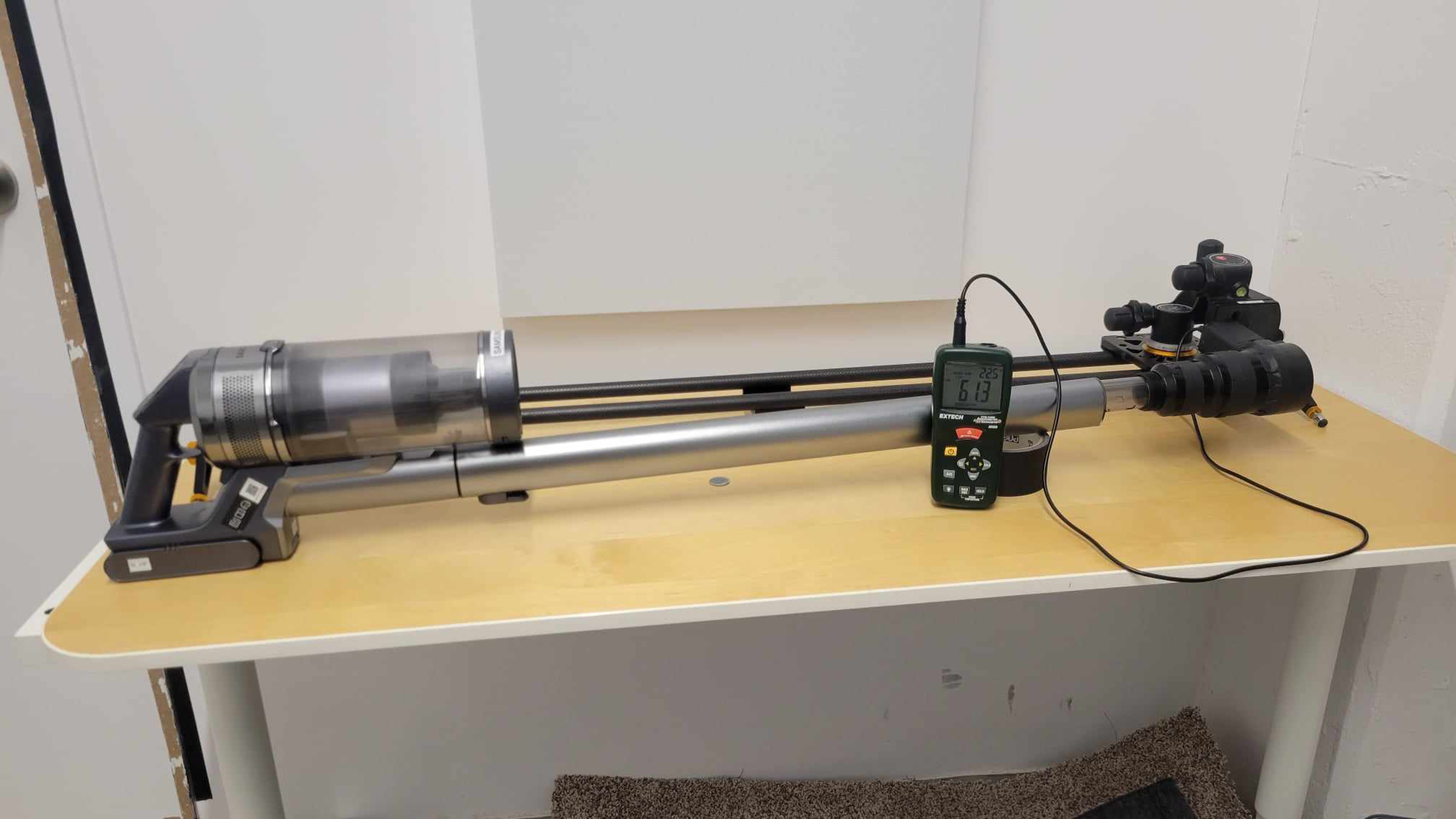
We observed that some vacuums with motors of similar power nonetheless delivered vastly different airflow measurements. Multiple factors can be at play here, but the proper utilization of our measuring device needs to be considered. The measuring instrument we use to test the airflow of the vacuums is an anemometer. This tool works by measuring the airspeed going through its vane and multiplying it by a set area. The combination of measured airspeed and the area configured in the anemometer gives us an airflow value. For this reason, the airflow measurement is highly dependent on the area set in the anemometer. It is important to control this area and to ensure that all vacuums will not be impacted by having a different area than the one set in the anemometer.
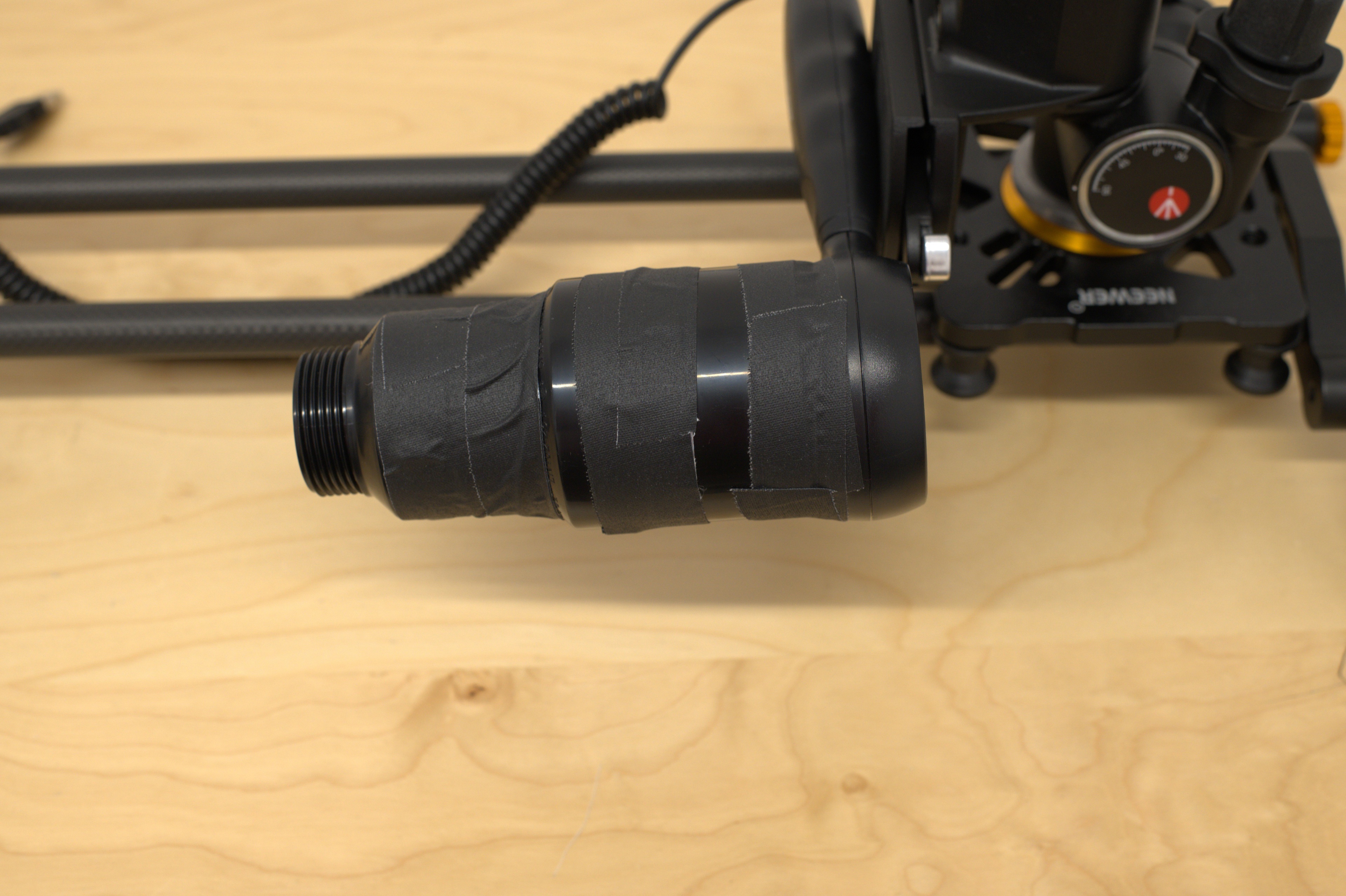
Changing the set area to match the tested hose diameter wouldn't solve all the potential issues that can arise when measuring from hoses that are smaller than the default anemometer vane. Hoses smaller than our anemometer vane would lead to inconsistent and inaccurate measurements because of improper fit between them. For example, measuring off-center from the anemometer test area could induce errors in the measured airflow value. This is why we decided to build a custom funnel to fit the anemometer's diameter. This funnel permits us to test hoses that are smaller in diameter than the vane of the anemometer without having to measure off the center of the anemometer and without modifying the set area. The funnel is chosen to be able to test most vacuums that we have in terms of hose diameter. We decided to go with a funnel to incrementally change the diameter to limit the losses caused by turbulence. Turbulence could occur where there is a radical change in diameter. Here, you can see an airflow table from the Miele Complete C3. The only variable that we changed for this table was the funnel arrangement.
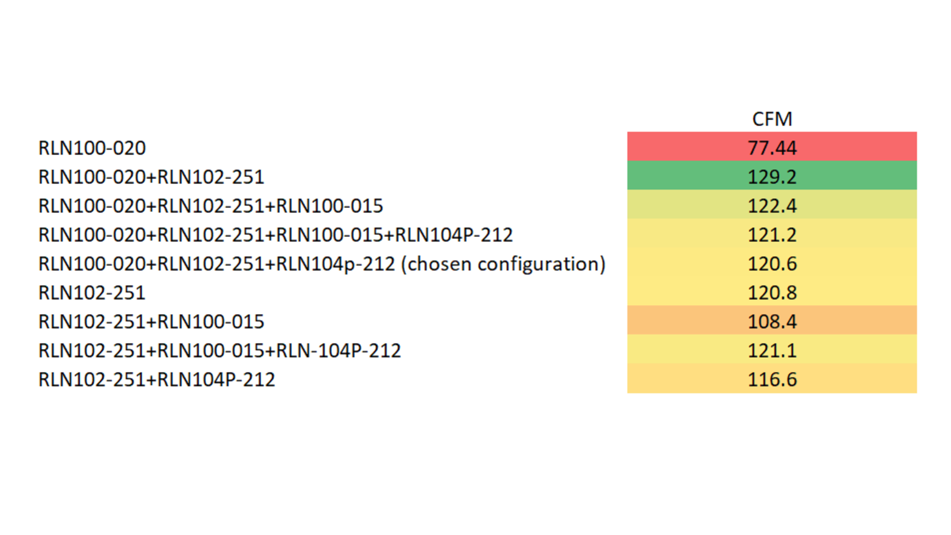
The airflow is lower with the chosen funnel due to its longer length, increasing the friction loss and slowing airspeed. Also, the different changes in diameter can induce losses due to the venturi effect, which stipulates that airspeed decreases as the diameter of the vessel through which it passes increases. In our case, we go from a 2" diameter (diameter of the vane) to a 1 ½" diameter. This phenomenon and the friction loss explain why we see lower airflow results with the selected configuration. This desired difference in diameter governed the length of the funnel.
This photo illustrates how some of the vacuums we tested have hoses that are too small to use the other funnel configuration, which yielded the highest overall airflow in preliminary testing.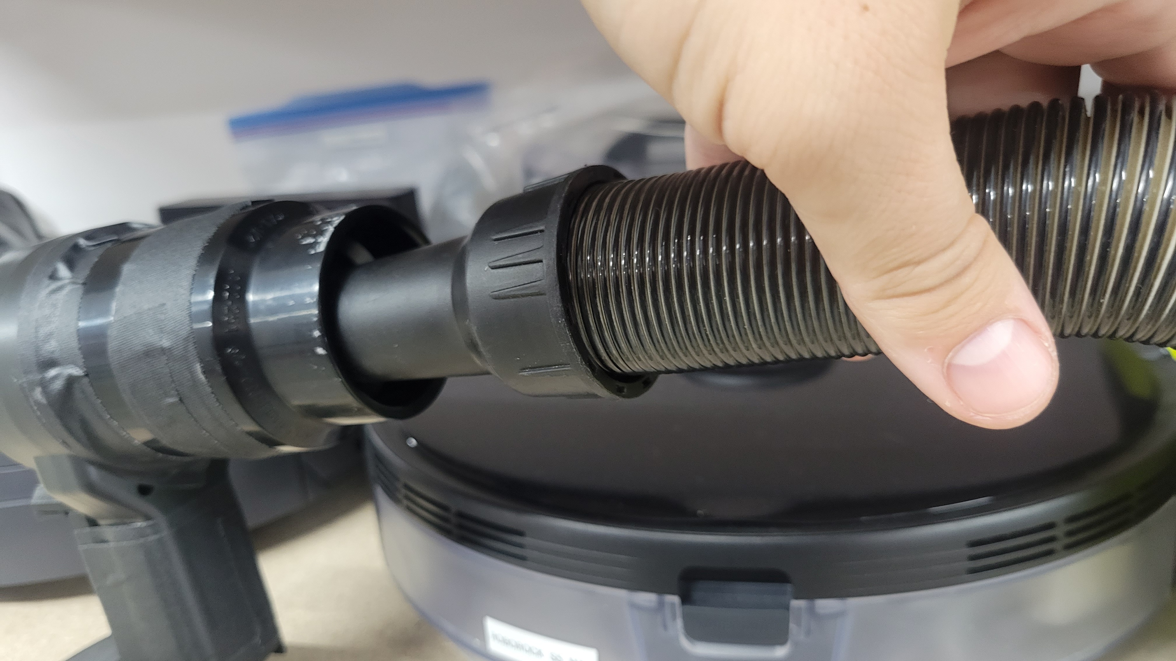
Although the chosen funnel arrangement for the anemometer didn't provide the highest airflow value we could measure, it did make it easier to have the same distance and diameter to measure from, leading to better results comparability.
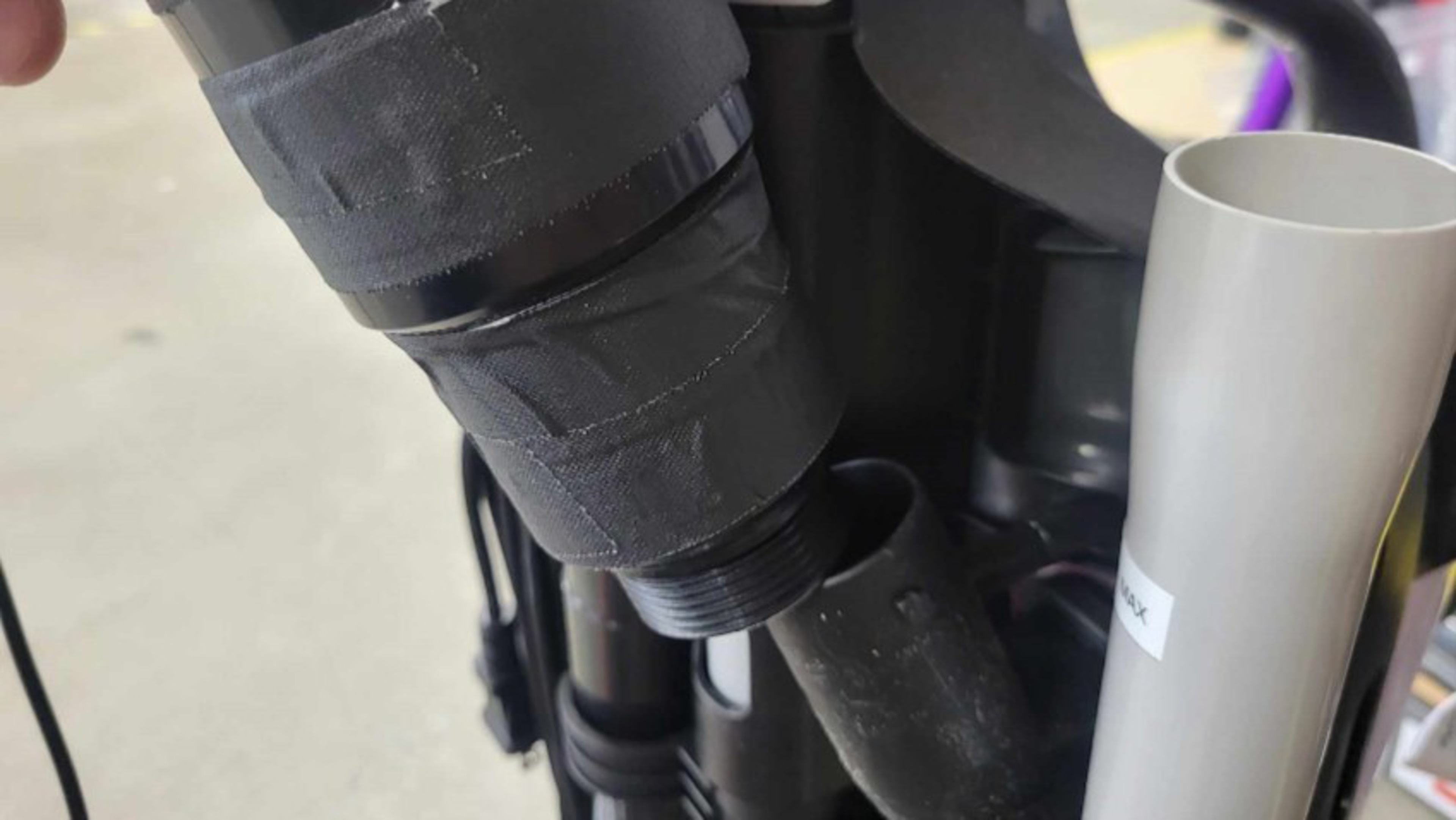
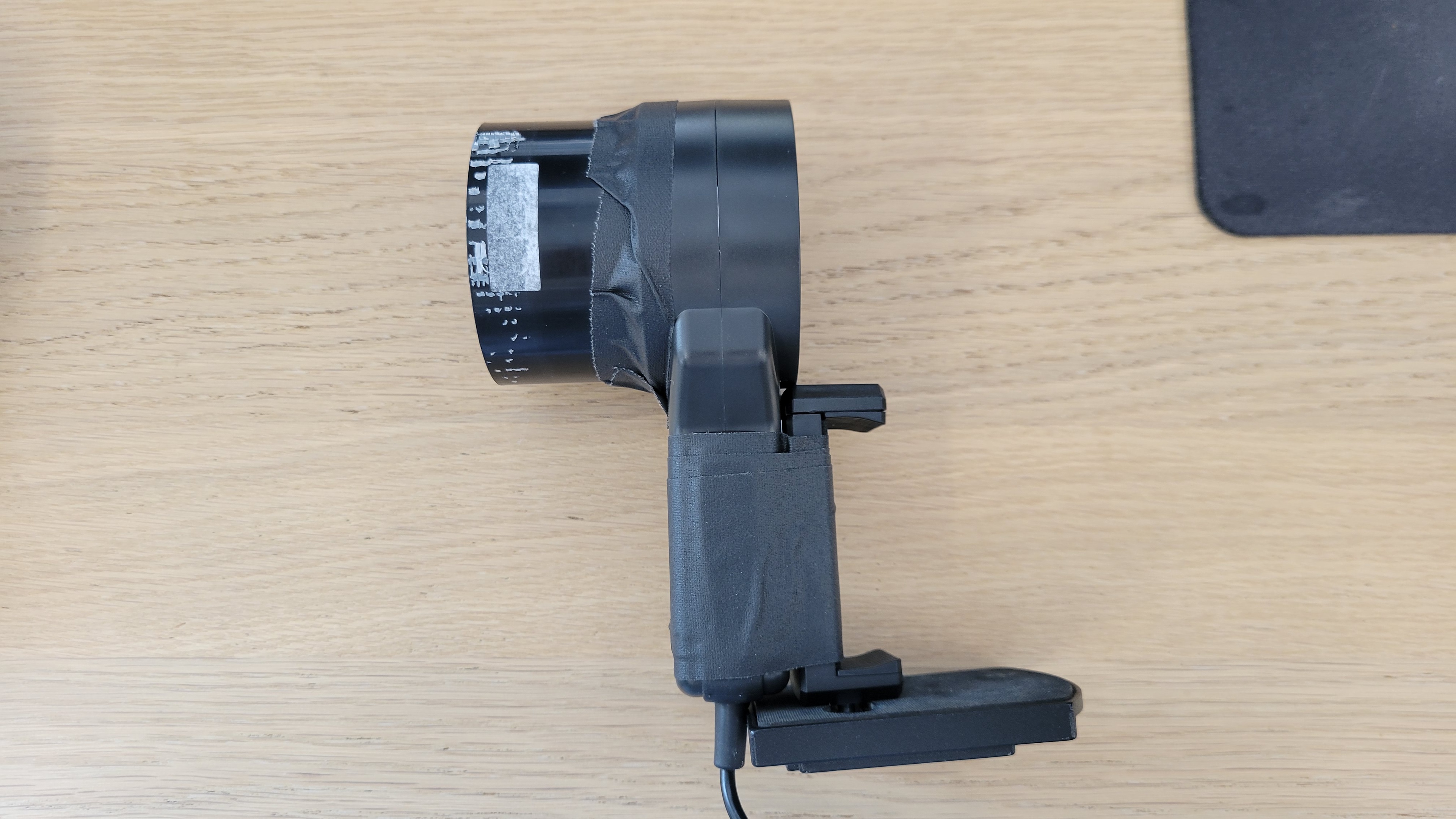
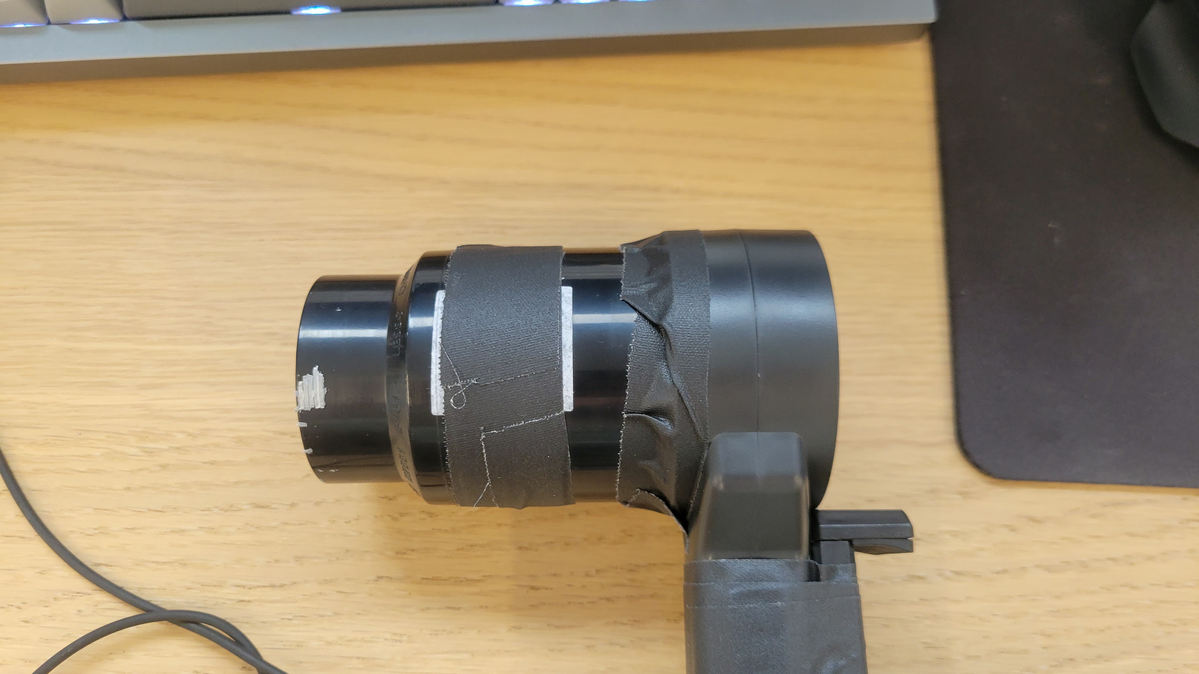
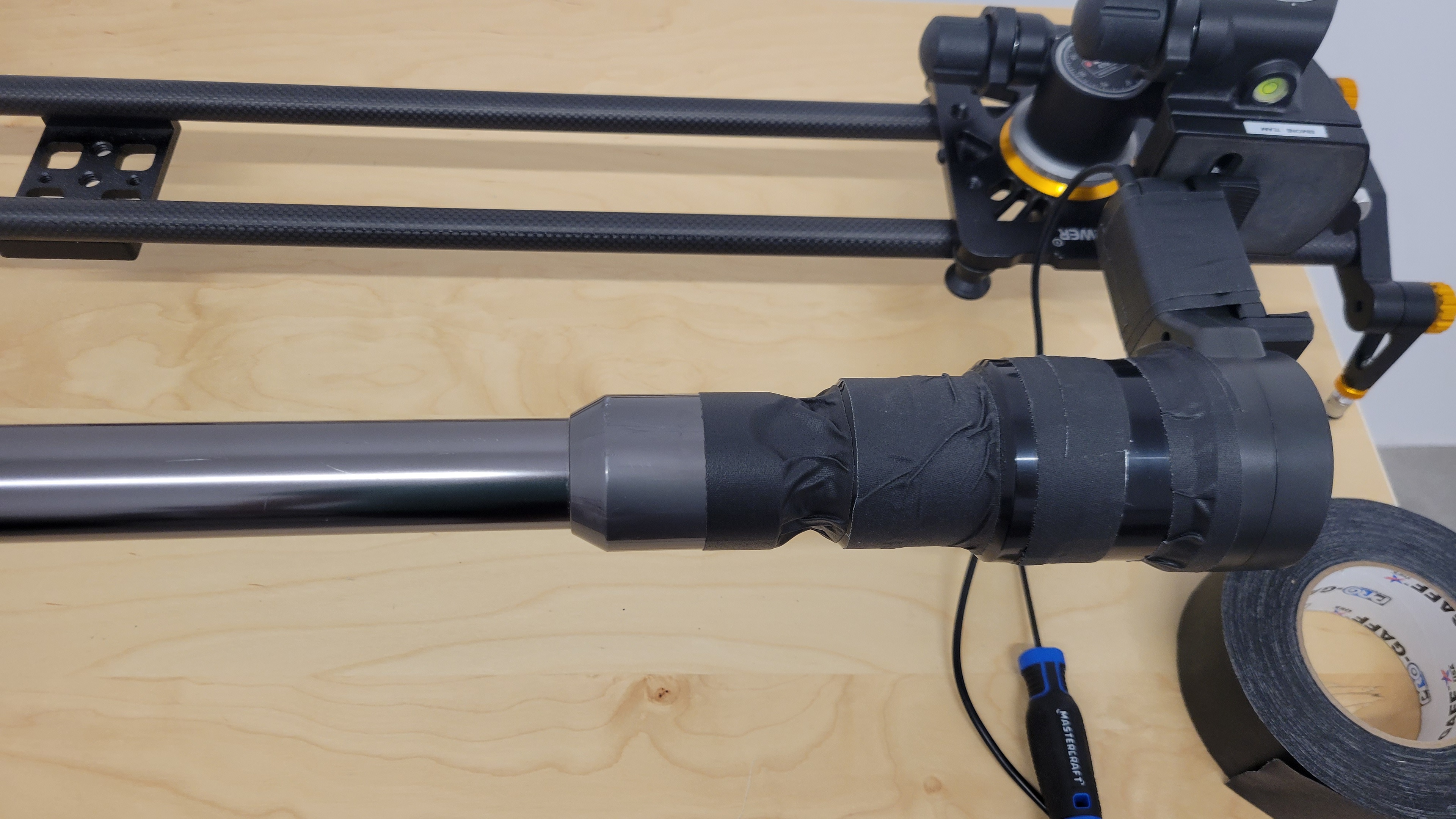
We further validated the choice of the funnel by testing the airflow through the Milwaukee M18 FUEL, a vacuum with one of the largest diameter hoses. Herein, we compared anemometer measurements with and without the anemometer tube and with and without the added funnel. As shown in the following picture, without the funnel, the Milwaukee hose very loosely fits inside of the RLN100-251 tube, yielding erroneous airflow measurements.
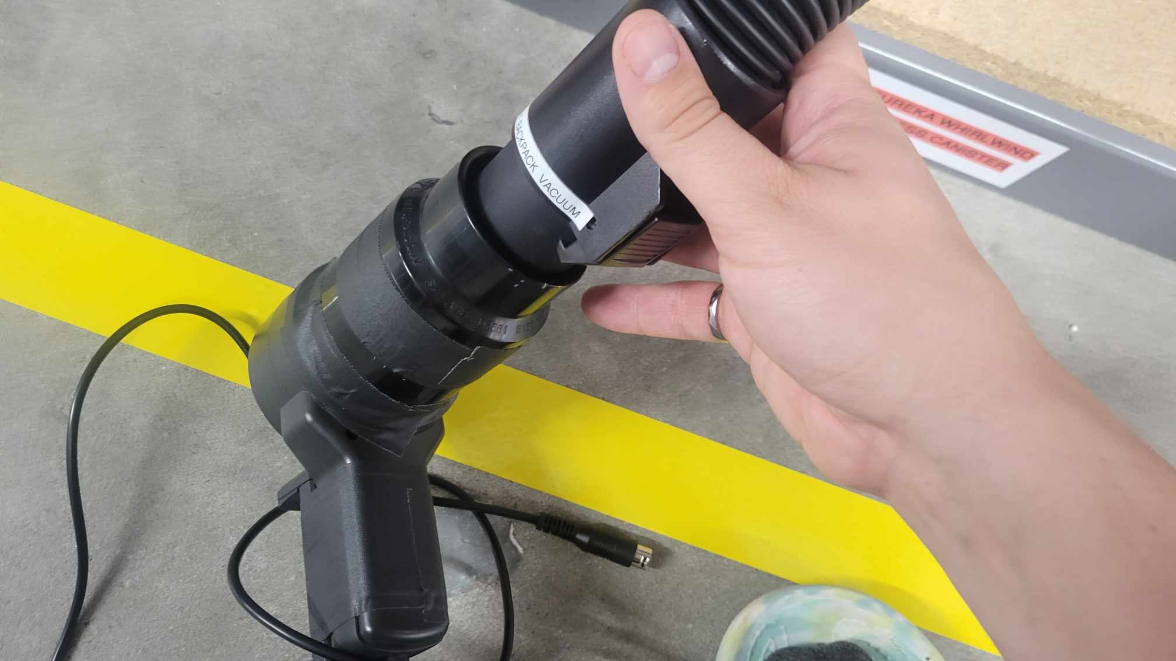
Next, sealing with tape the Milwaukee hose to the RLN100-020+RLN102-251 funnel yields much higher airflow measurements of 80 CFM. Finally, looking at the table below, we can observe that the chosen funnel ultimately serves a similar purpose to sealing to an inadequate diameter; the airflow measurements taken with the chosen funnel compared to a sealed funnel with an inadequate diameter can be considered equivalent.
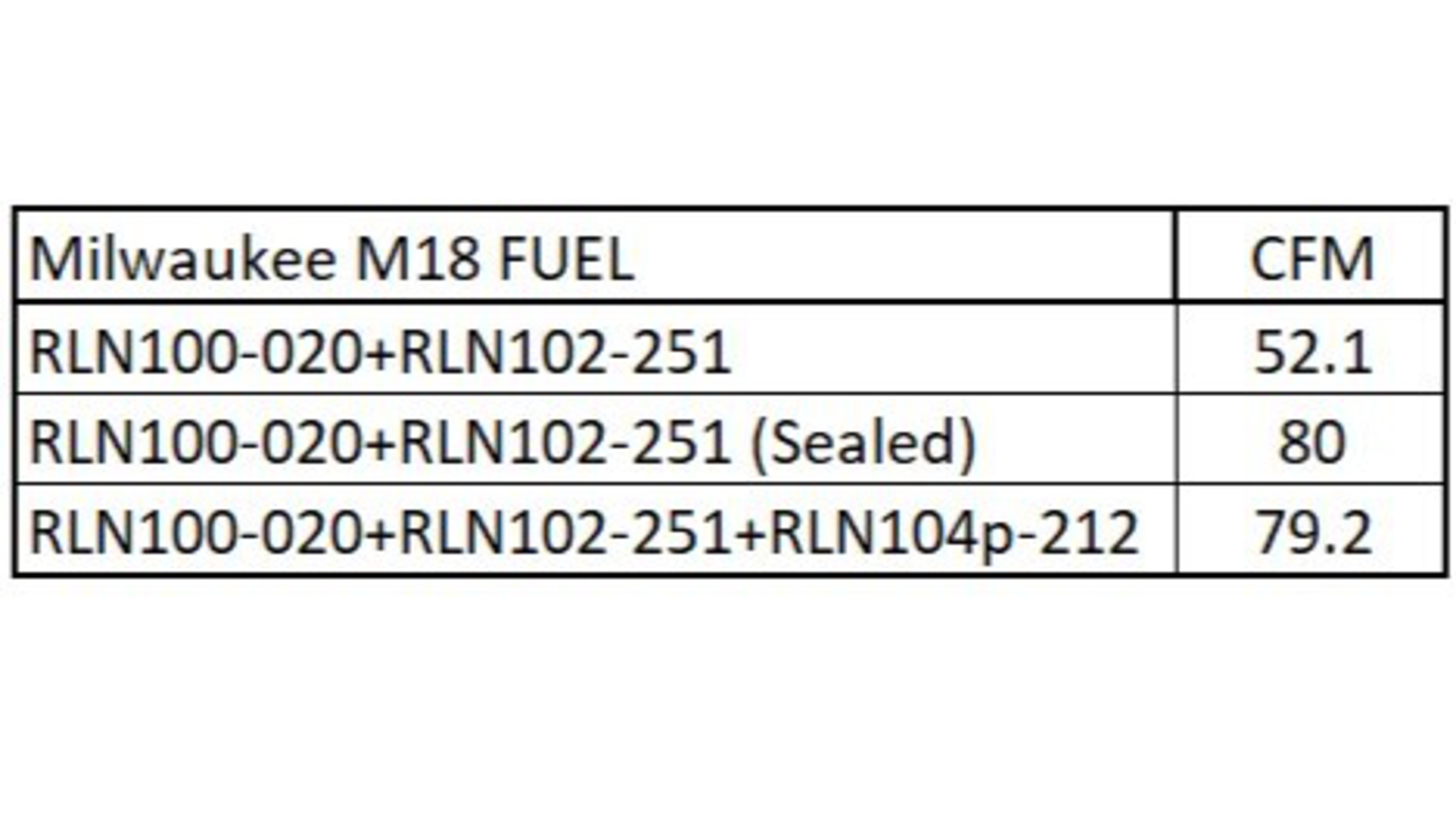
We note that the choice of the funnel does impose an upper limit of 5.7 cm to the hose's inner diameter that could reliably be measured with this methodology. The testing of vacuums with large diameter hoses, like shop vacs, would need to be separately considered. Nonetheless, the funnel allows us to take measurements consistently for all our current vacuums.
Effect Of Sealing The Vacuum Hoses To The Funnel With Tape
To confirm if vacuums with internal hoses have a sufficiently tight seal with the funnel to yield reliable airflow measurements, we had to investigate their impact on our measurements with our funnel. Some vacuums with slightly more unique design aspects, like some Dyson models, require that the joint between the stick and the funnel be taped to achieve a proper seal that allows the anemometer to measure all the airflow generated by the vacuum.
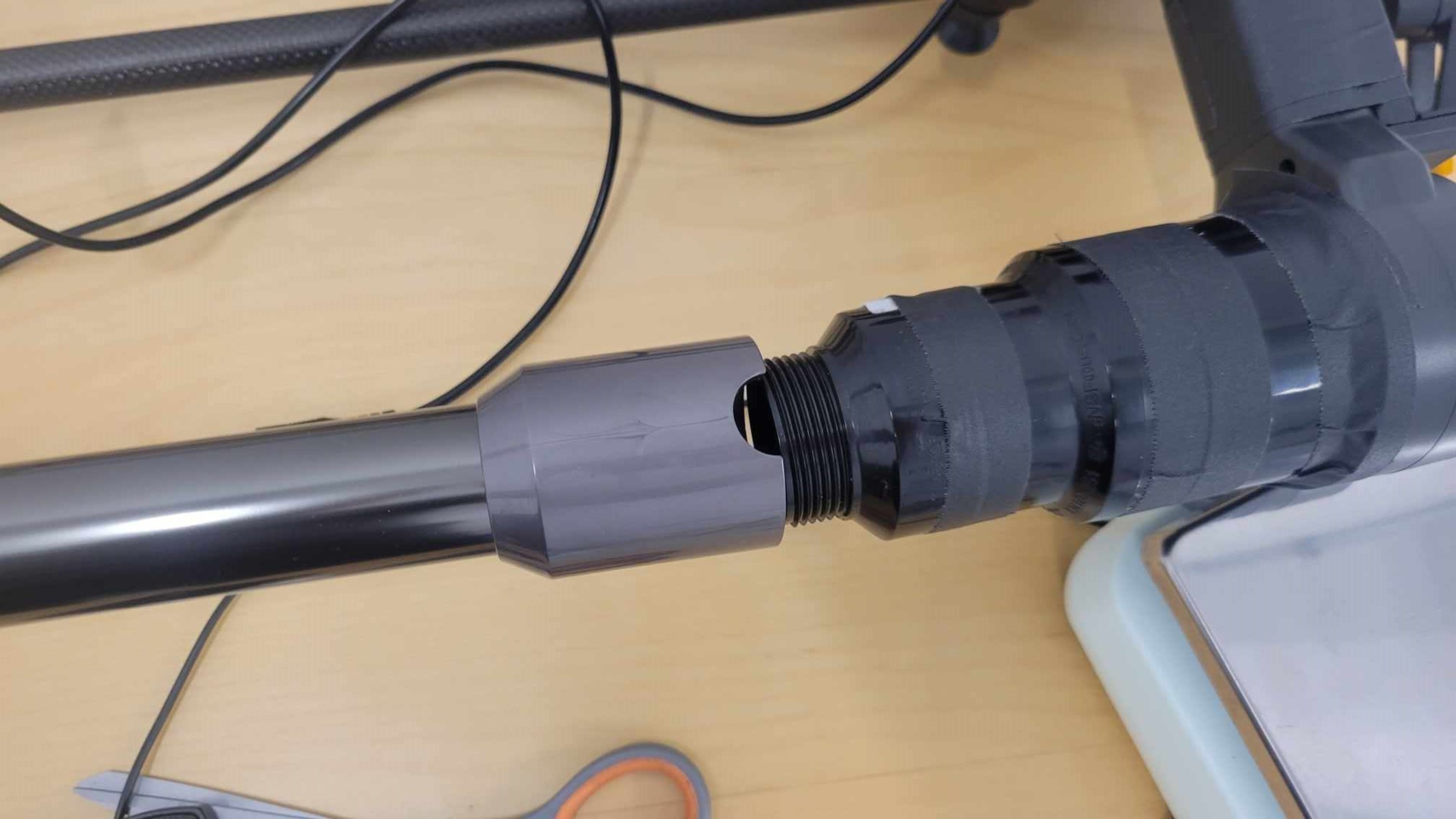
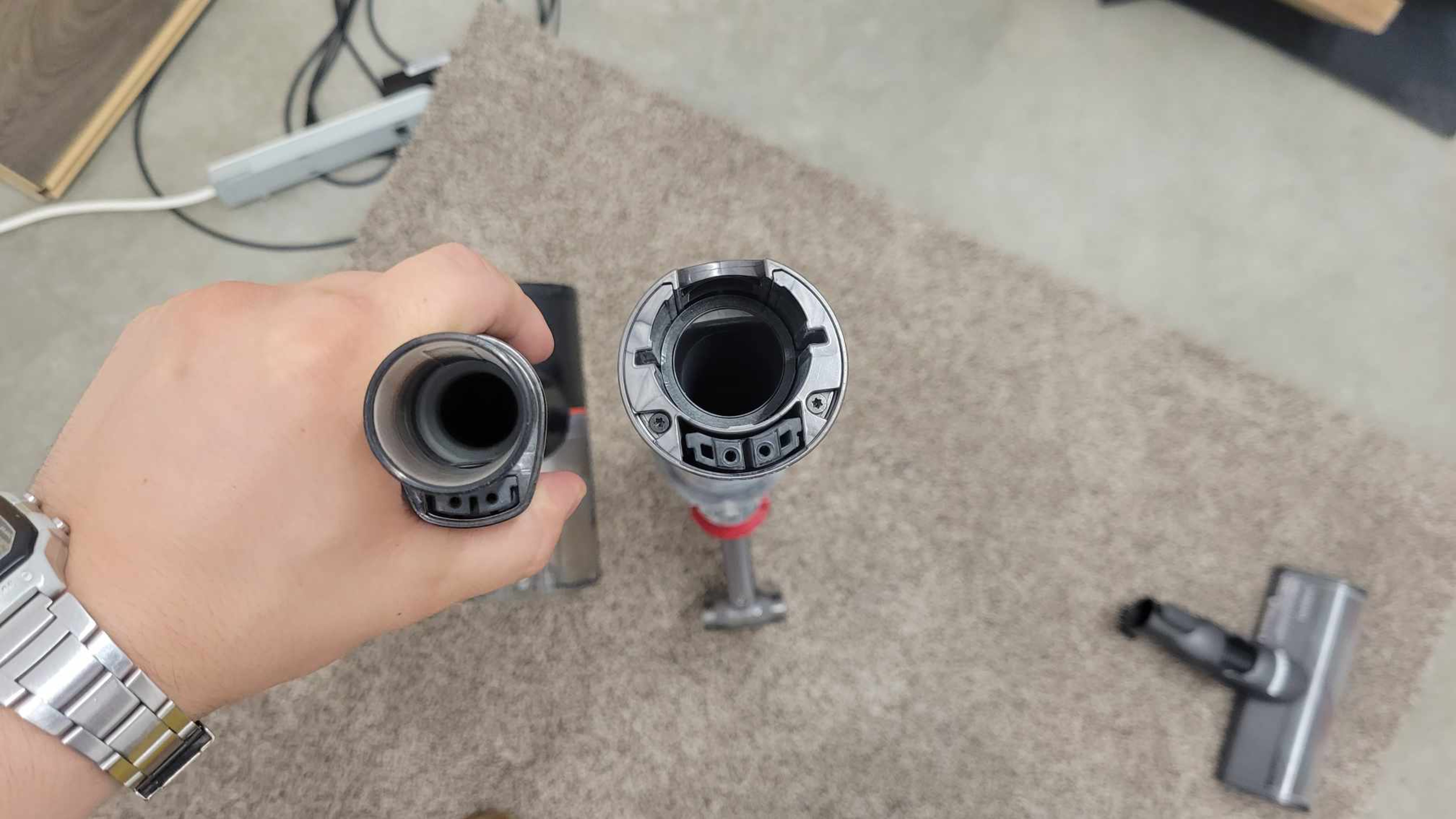
The following photo demonstrates the difference between the internal hoses of the LG CordZero A9 and the Dyson V11. On the LG A9, the attachment point between the wand and floorhead sticks out from the wand. In the Dyson V11's case, the attachment point is recessed inside the wand.
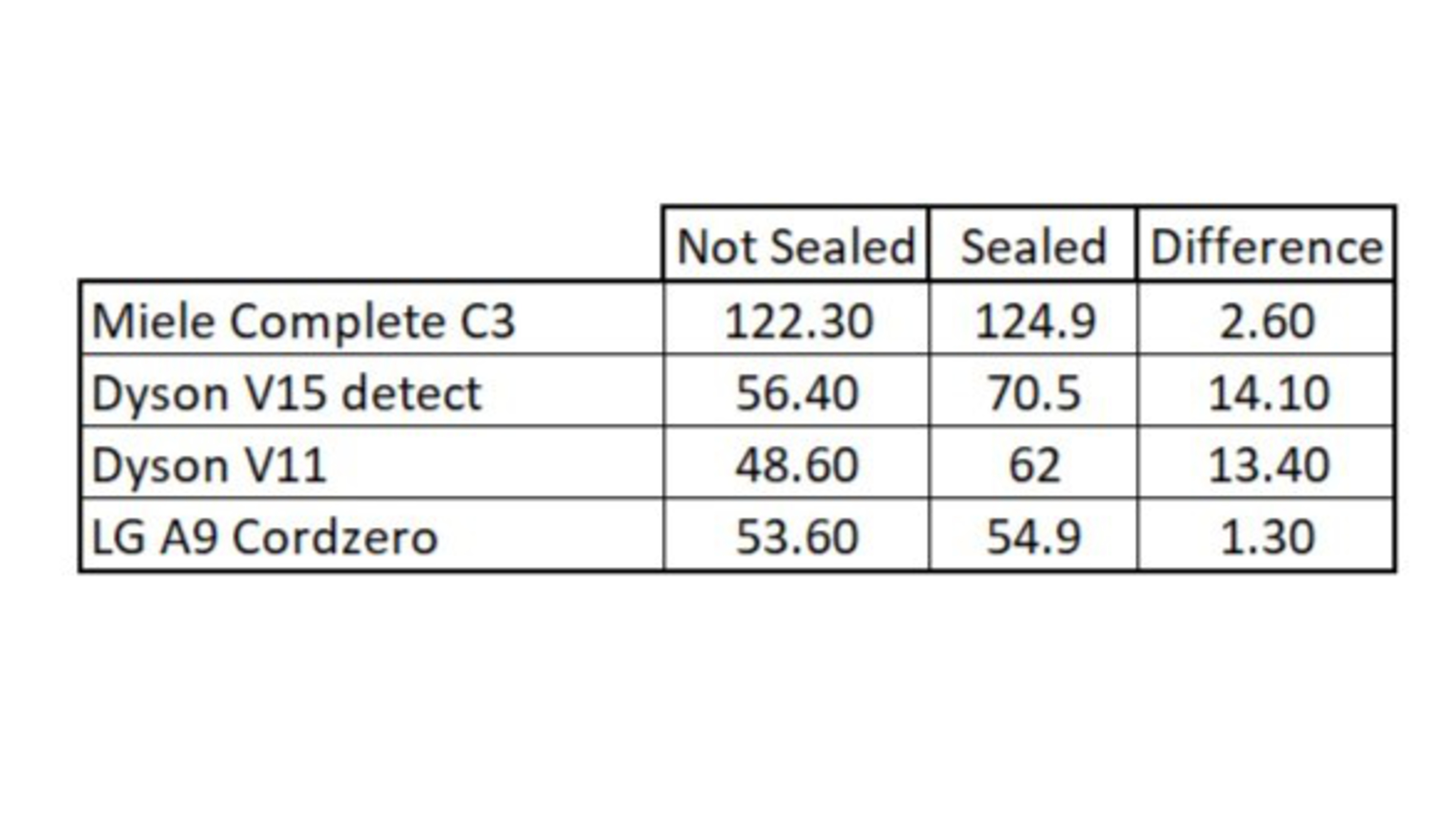
We observed an increase of 14.10 CFM and 13.40 CFM when we used tape to seal the Dyson V15 and the Dyson V11, respectively, because of the reduced leaks with the funnel. Conversely, the use of tape to seal vacuums with more conventional wands/hoses like the LG A9 only yielded an increase in measured airflow of 1.3 CFM. This increase is negligible because the hose already sufficiently seals with the funnel.
In the following table, we can see the differences between a sealed and unsealed stick. For example, the LG A9 and Miele C3 have standard hoses that fit well to our funnel without having to seal them together. The negligible increase in airflow can confirm this. For the two Dysons, however, we saw that the sealing was beneficial to their measured airflow. The addition of sealing tape results in a more robust airflow test since we can test vacuums with more unique hose/wand designs.
For these reasons, we decided to seal with tape the vacuum hoses and sticks that wouldn't mate well with the funnel like the Dyson vacuum's wands.
Solution
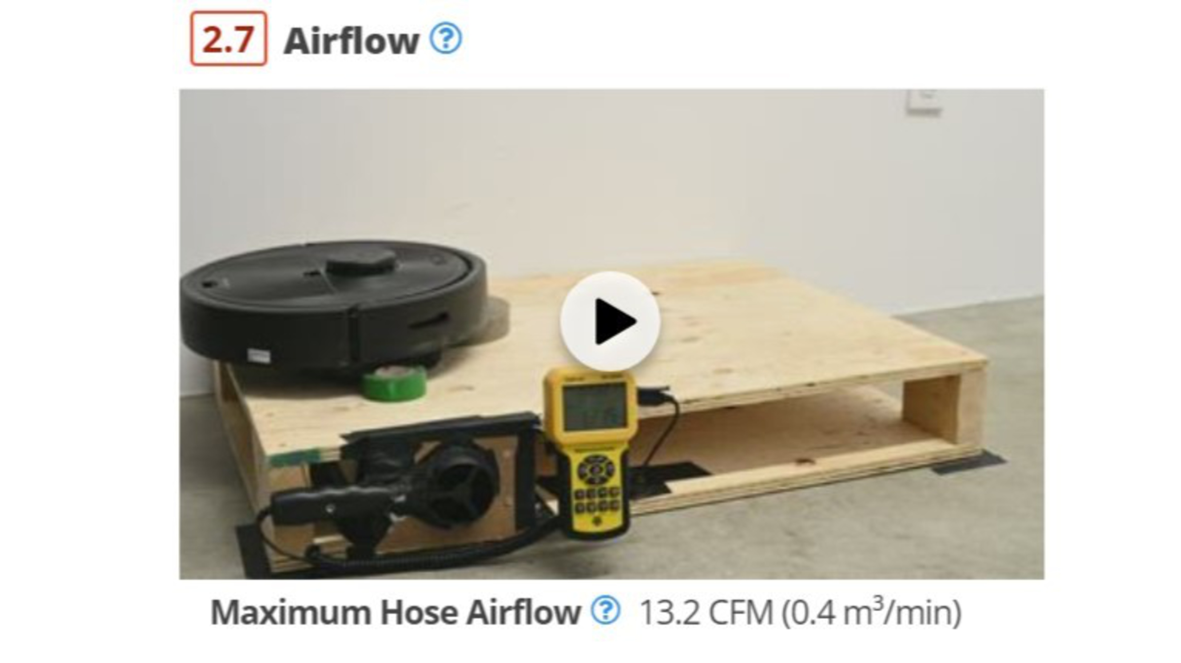
Following these explorations, we developed a testing methodology for measuring vacuum airflow. We record a video of robot and non-robot vacuums hooked up to their respective airflow measurement rigs, clearly displaying the anemometer readings. This clearly shows the vacuum in testing, where the value comes from, and how the vacuum was mounted to the funnel. For non-robot vacuums, the test starts by removing all attachments from the hose and putting the end of the hose/wand on the funnel of the anemometer.
Once the hose is seated properly on the end of the funnel, the vacuum is switched on to its most powerful setting. The test continues until the value measured by the anemometer stabilizes. This stable value is what is reported in the review.
For robot vacuums, the test consists of placing the robot on a rolled foam that borders its head. The foam helps seal the robot to the test rig so that the anemometer measures all the airflow that the robot generates.
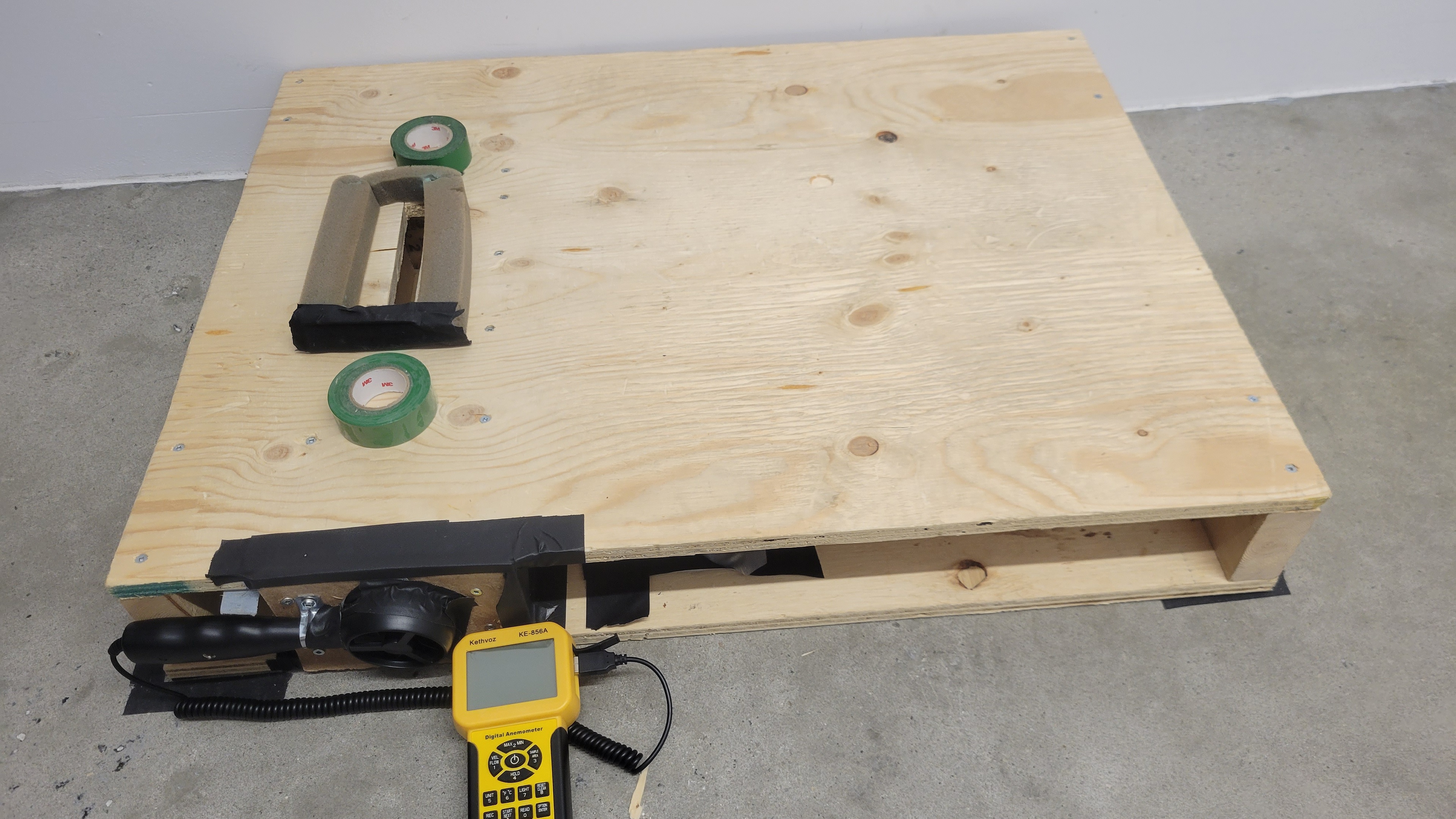
The robot is held above the platform with spacers so its wheels are not touching. The robot proceeds through its normal programmed movements while remaining stationary during the airflow tests. The robot is switched to its most powerful setting, and the test continues until the measured value stabilizes.
Data Analysis
Observing Vacuum types
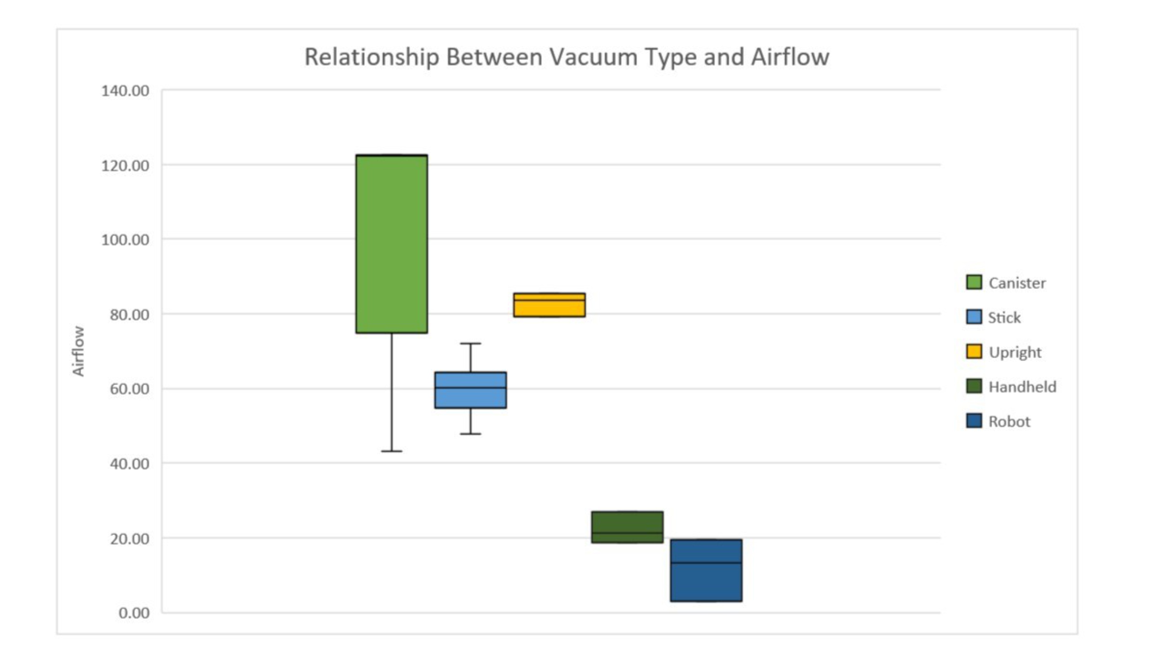
Due to their simpler designs and capacity for large, powerful motors, canister vacuums were expected to generate the most airflow, followed by upright, stick, and robot vacuums. The results are consistent with these assumptions. The following graph presents the measured airflow by vacuum type of 25 vacuum we initially tested.
Creating more airflow at their hose was expected for canisters. They can generate a high airflow because they typically have a powerful motor and a hose in line with the motor. In this picture of the Miele C3 Complete, we can see that the motor is directly in line with the bag (the filter has been removed to better illustrate its design).
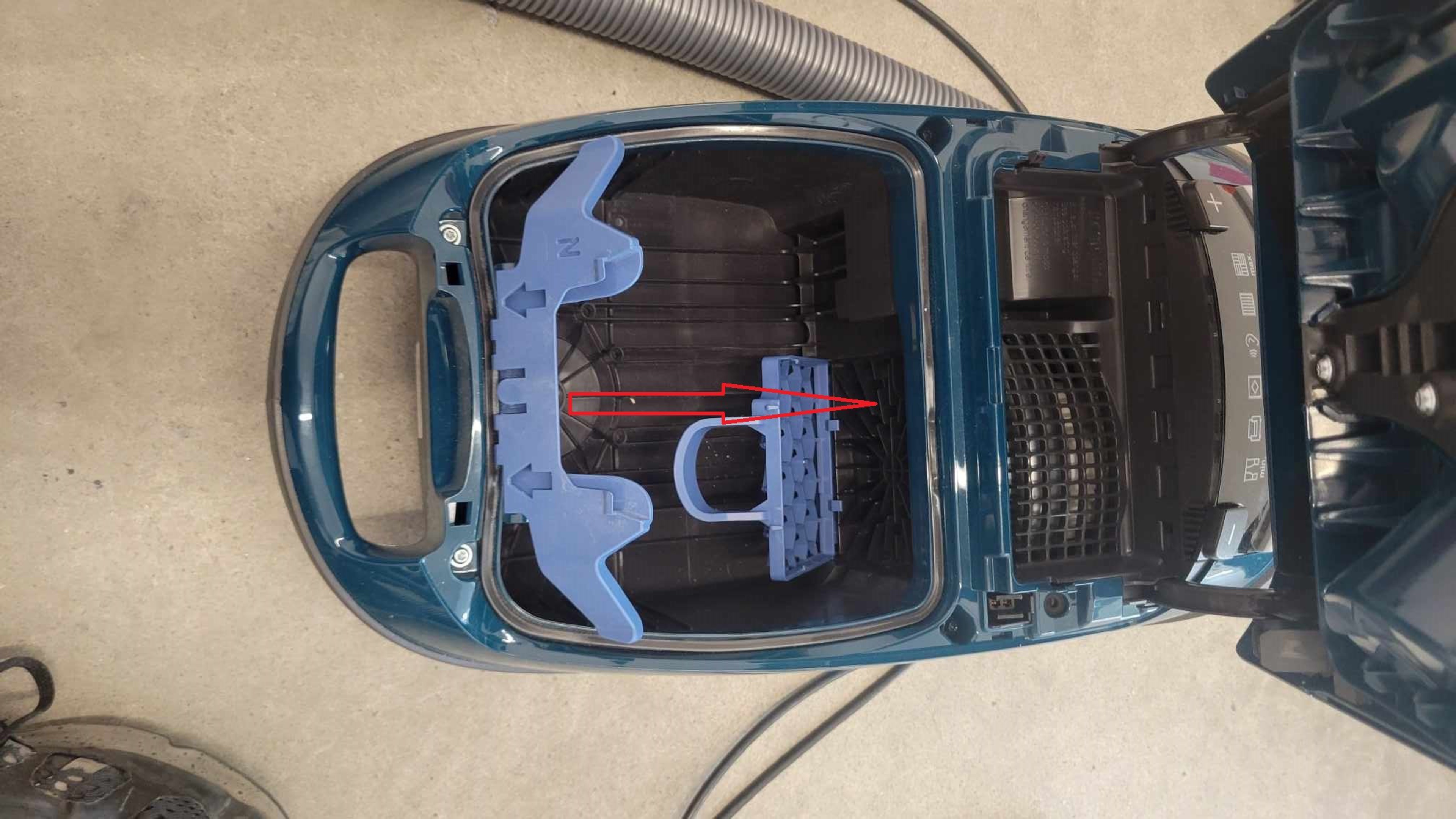
As such, canister vacuums make efficient use of airflow with minimal losses. The previous graph also shows that the canisters have the largest range of measured airflow. This is due to the measurements taken on the Airsign HEPA Vacuum. While this vacuum's performance is in line with what we were expecting, it is considered an outlier for the purposes of this comparison. We investigated the Airsign due to the low airflow measurement we'd obtained and discovered that this was caused by the vacuum's restrictive dirtbag design. With the dirtbag installed, we registered 43.1 CFM, but after removing the bag, we measured 116.3 CFM, clearly illustrating the importance of a good bag design in bagged vacuums. Uprights can have the same motors as a canister, but they typically have more convoluted paths that the air must flow through to reach the end of the hose. We can see a clear example of this with the following image of the Miele U1 Powerline, with the superimposed red arrows showing the path the air needs to move through in the machine. We can see that there are a lot of corners and lengths that the air must follow to get to the hose and head.
This adds considerable resistance to the airflow. As an example, the Miele U1 and Miele C3 have the same motor but have drastically different airflow, and this is due to the bendy hose path in the U1. Sticks have lower airflow than canisters and uprights because their compact and portable designs leave little room for a powerful motor. Cordless stick vacuums were not expected to have high airflow since they are small battery-powered vacuums. Generally speaking, they also have smaller, lighter, and less powerful motors to reduce their weight as much as possible so they can be easily carried in one hand. Finally, robot vacuums are the vacuums that generate the least airflow due to their smaller size. They need to fit the motor and all the other parts in a small form factor, reducing the space the battery and motor can take.
Cordless vs Corded
Corded vacuums tend to have higher airflow since their electricity source is a household outlet rather than a battery. Cordless vacuums have more constraints in their motor choices and implementation since battery life is an important consideration. Indeed, the corded vacuums present higher airflows than the cordless vacuums we tested, as shown in the following figure. 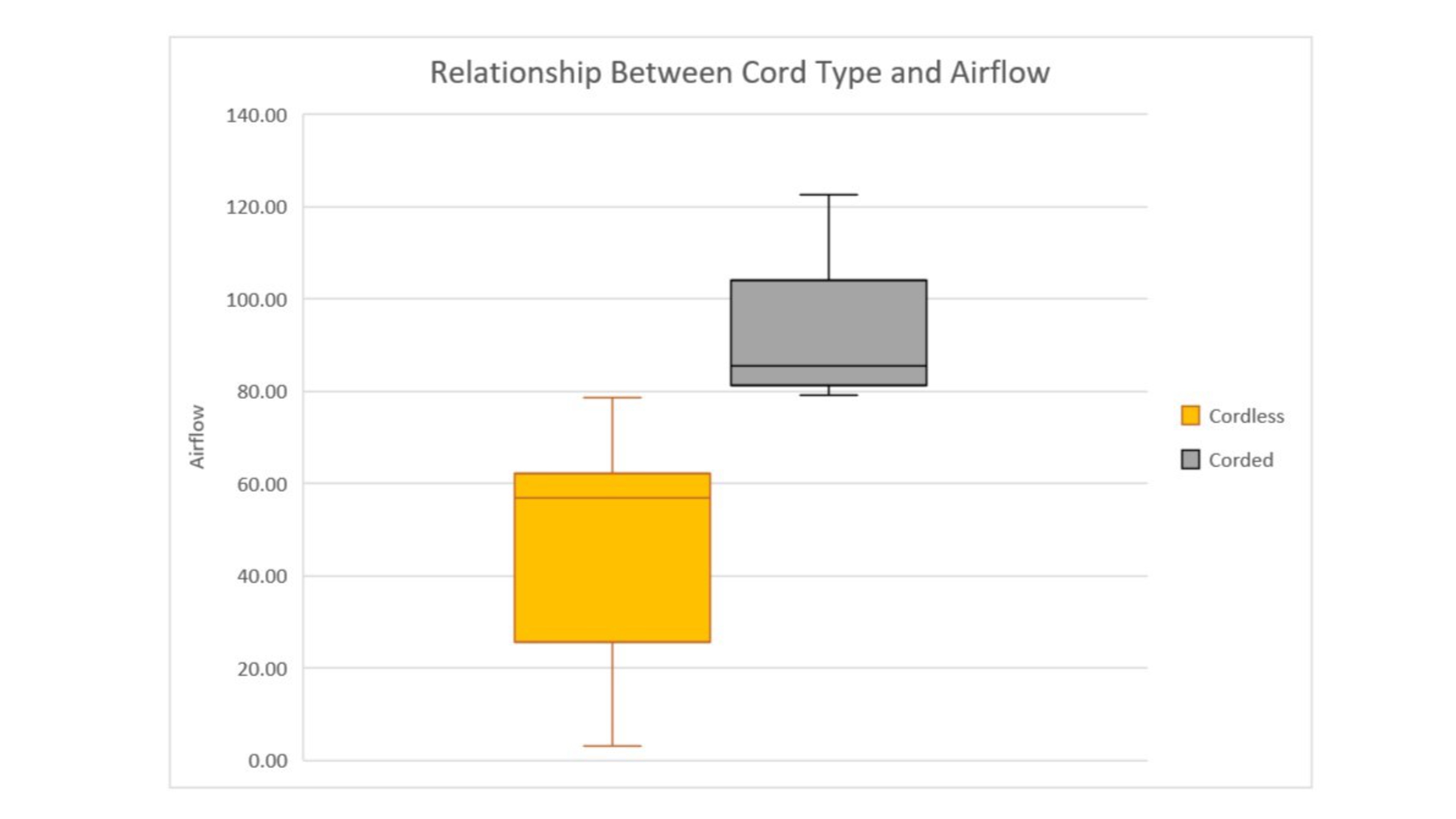
Dyson Models Comparison
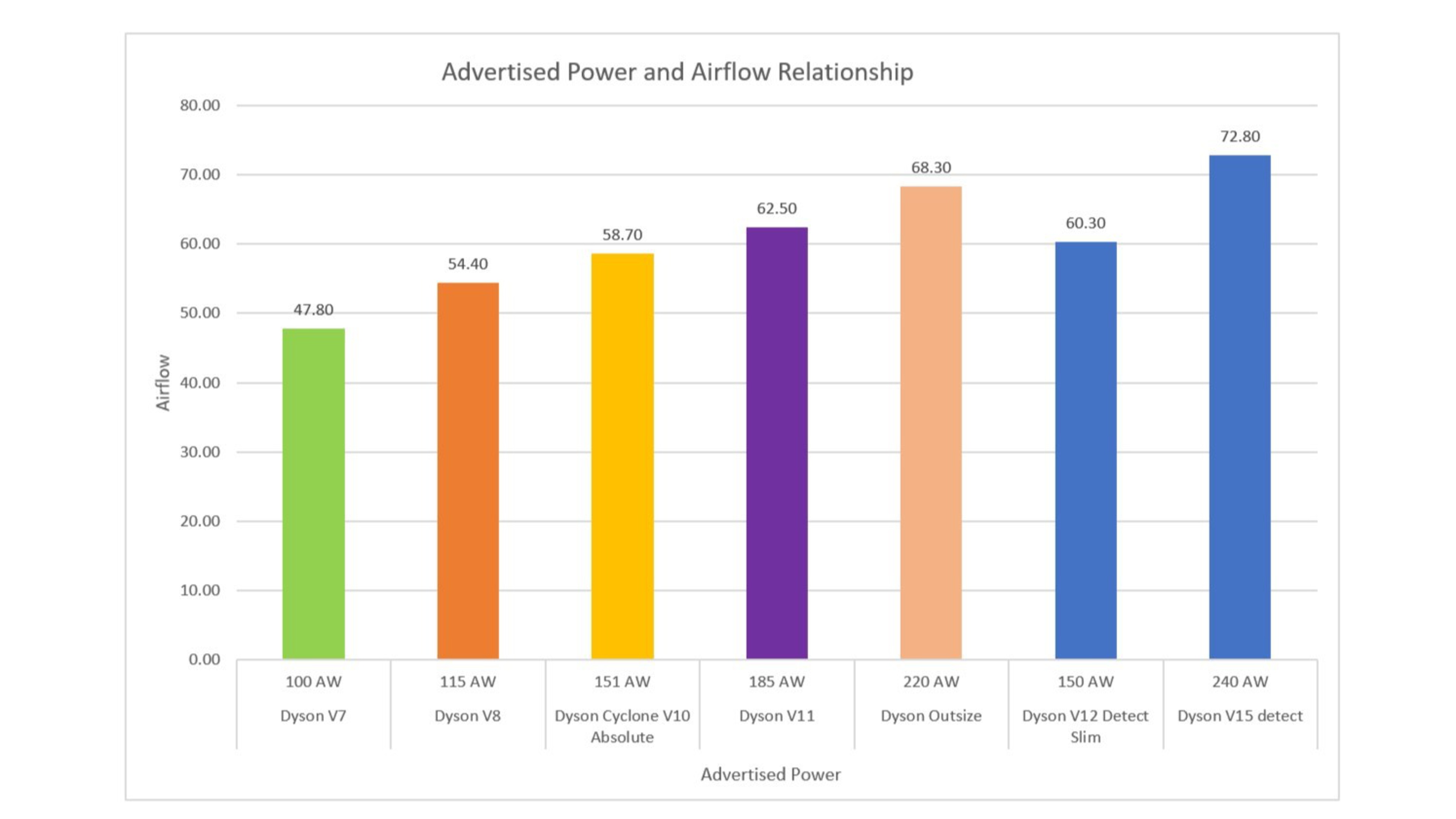
We further explored the relationship between advertised power and airflow by focusing on a single manufacturer: Dyson. In doing so, we can compare vacuums with a similar design. The following figure demonstrates that newer Dyson models tend to have higher advertised power and, ultimately, higher airflow[4]. Some older models are shown to be less efficient, like the Dyson V11, compared to the Dyson V12, which is three years newer. The V12 has lower advertised power than the V11 but generates almost as much airflow as the V11 does with less power. This could be due to the design changes that we saw between them. They advertised some changes on their website that could explain the higher efficiency with newer designs.
Test Variance And Limits
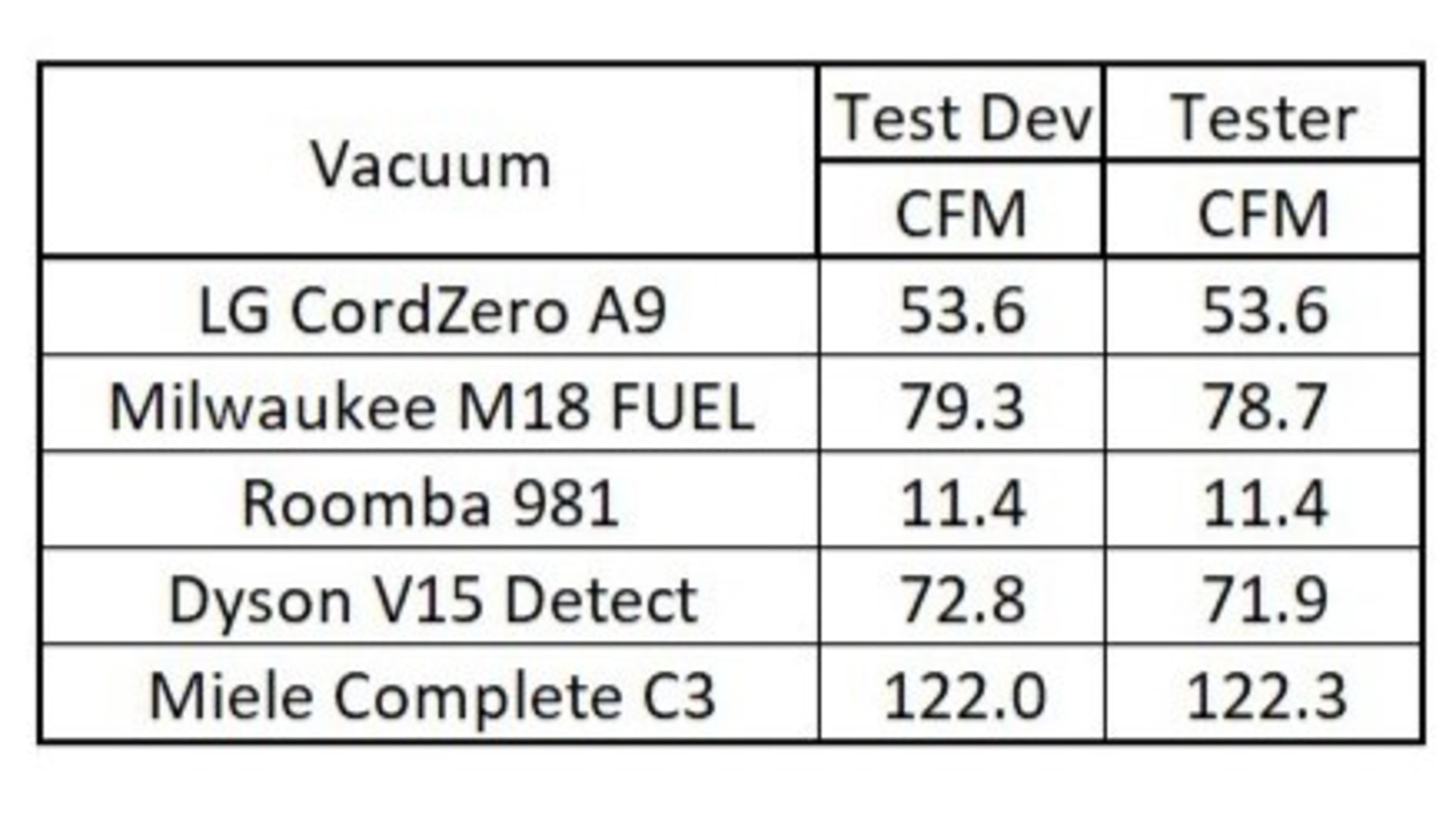
Difference Between Two Testers
The test results collected separately by two testers (the Test Developer and the Tester) show that the methodology is robust and not operator-dependent. The comparison in the following table indicates that the developed methodology will yield comparable results across various vacuums even if evaluated by different testers.
Battery
The battery life of a vacuum can impact the airflow performance of the vacuum. We account for this by charging the vacuum to its maximum capacity before testing.
Debris Level
The debris level in the bag, filter, or dirt compartment could affect the airflow. As such, we measure airflow before conducting the debris pick-up tests so the vacuum is clean and empty. This way, we can ensure that the filter is new and not clogged and that the bag or dirt compartment is empty.
Funnel Limitation And Compromise
The funnel is a compromise to consistently fit all the vacuums we test using the anemometer. Making it small enough to fit the smaller hoses makes it longer, resulting in friction loss. For example, we saw a variation of 7% with the Miele Complete C3, which is considered to have good airflow when varying the funnel configuration. This limitation imposes a reduction on the theoretical airflow generated by the vacuum.
Measurement Location Compromise
Measuring the airflow from the hose is a compromise compared to measuring it straight at the motor. Because there are losses in the hose, we don't measure the 'true' maximum airflow the motor can generate. One of the differences when choosing to measure at the motor is that it removes the impact of the hose length and design on the measured value. The way we've decided to measure from the hose on the funnel enables us to measure all our vacuums but also consider some losses due to the path the air must travel. For example, with our testing on the Miele C3, we saw a decrease of 9% between measuring at the motor versus measuring at the opening of the flexible hose.
Impact Of These Limitations On The User
During our testing and validation processes, we saw that sealing the hose could help in some cases and didn't significantly impact the measurements in others, with some vacuums only displaying a difference of around 1 CFM when comparing sealed and non-sealed testing. We designed the airflow measurement test to produce consistent results, regardless of who was conducting said test, but differences of around 1 CFM are to be expected with different testers. If we account for all these different limitations, we can say that two vacuums with less than 3 CFM between are delivering the same level of performance.
Conclusions
With the implementation of an airflow test, our reviews will now include an objective measurement of the capabilities of the vacuum and its motor. To obtain more comparable results, we test by using an anemometer with a custom funnel attachment. The results from the airflow test should be interpreted as a raw performance value of the vacuum. We need to be careful when comparing robot vacuums and normal vacuums. Since the test setup is different between them, we can't assume that both are on the same even playing field.
In general, this test contributes to painting a picture of the performance of a vacuum in a comparable way.
Pros and cons:
+ The setup and equipment provide good measurement consistency.
+ The value reported can account for differences in design that impact the airflow generated by the motor.
- The difference in testing setup leads to unreliable measurement comparisons between robots and standard vacuums.
- The value reported is lower than what the motor can generate due to funnel friction loss and standardized measurement location.
Sources
[1] BMP Industrial Supply. Ametek Lamb 122178-18 Blower/Vacuum Motor 6VMX3. [Online] Available at: https://www.blowermotorsplus.com/Ametek_122178_18_Lamb_Blower_Vacuum_Motor_p/122178-18.htm [Accessed 2023-09-04]
[2] The Engineering ToolBox (2005). Air - Volume vs. Temperature. [Online] Available at: https://www.engineeringtoolbox.com/air-temperature-volume-d_853.html [Accessed 13/05/2023]
[3] Ristenbatt. Miele C3 Brilliant Vacuum Cleaner. [Online] Available at: https://www.ristenbatt.com/xcart/Miele-C3-Brilliant-Vacuum-Cleaner-with-SEB-236-Specifications.html [Accessed 13/05/2023]
[4] Dyson. [Online] Available at: https://www.dysoncanada.ca/en [Accessed 15/06/2023], multiple pages consulted for all the different Dyson vacuums' tested specifications.
REVISION TRACKING:
Date Created: October 20th 2023
Original Author: Pierre-André Girard
Rev. 1
Date: January 10th 2024
Author: Pierre-André Girard
Change: Removed section talking about Miele vortex motor.
Recommended Articles


